6![]()
![]()
![]() EN
EN![]()
![]()
![]()
![]()
![]()
![]()
![]()
![]()
![]()
![]()
![]()
![]()
![]()
![]()
![]()
![]()
![]()
![]()
![]()
![]()
![]()
![]()
![]()
![]()
![]()
![]()
![]()
![]()
![]()
![]()
![]()
![]()
![]()
![]()
![]()
![]()
![]()
![]()
![]()
![]()
![]()
![]()
![]()
![]()
![]()
![]()
![]()
![]()
![]()
![]()
![]()
![]()
![]()
![]() INSTALLING
INSTALLING![]() YOUR
YOUR![]()
![]() NEW
NEW![]()
![]() VCR
VCR![]()
![]()
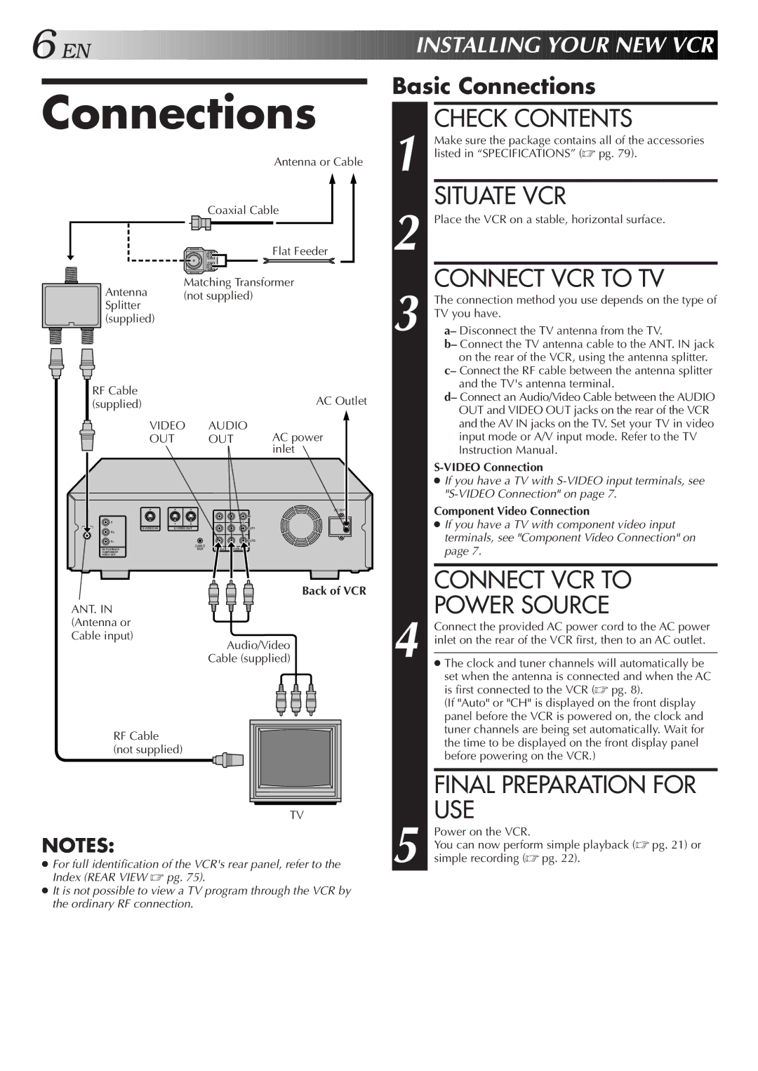
Connections
Antenna or Cable
Coaxial Cable
Flat Feeder
Matching Transformer
Antenna (not supplied) Splitter
(supplied)
|
|
|
| RF Cable |
| AC Outlet | |||
|
|
|
| (supplied) |
| ||||
|
|
|
|
|
|
| VIDEO | AUDIO | AC power |
|
|
|
|
|
|
| |||
|
|
|
|
|
|
| |||
|
|
|
|
|
|
| OUT | OUT | |
|
|
|
|
|
|
| |||
|
|
|
|
|
|
|
|
| inlet |
|
|
|
|
| AC IN |
|
|
|
|
| IN |
Y |
| 1 | 2 | R | L |
ANT. IN | S VIDEO IN | S VIDEO OUT |
| OUT1 | |
Pb |
|
|
| R | L |
|
|
|
| ||
Pr |
|
|
|
| OUT2 |
|
|
| CABLE |
|
|
DV PLAYBACK |
|
| BOX | VIDEO | AUDIO |
COMPONENT |
|
|
|
|
|
VIDEO OUT |
|
|
|
|
|
Back of VCR
ANT. IN (Antenna or
Cable input)
Audio/Video Cable (supplied)
Basic Connections
| CHECK CONTENTS |
| Make sure the package contains all of the accessories |
1 listed in “SPECIFICATIONS” (☞ pg. 79). | |
| SITUATE VCR |
2 Place the VCR on a stable, horizontal surface. | |
3 | CONNECT VCR TO TV |
The connection method you use depends on the type of | |
TV you have. | |
a– Disconnect the TV antenna from the TV. | |
| b– Connect the TV antenna cable to the ANT. IN jack |
| on the rear of the VCR, using the antenna splitter. |
| c– Connect the RF cable between the antenna splitter |
| and the TV's antenna terminal. |
| d– Connect an Audio/Video Cable between the AUDIO |
| OUT and VIDEO OUT jacks on the rear of the VCR |
| and the AV IN jacks on the TV. Set your TV in video |
| input mode or A/V input mode. Refer to the TV |
| Instruction Manual. |
●If you have a TV with
Component Video Connection
●If you have a TV with component video input terminals, see "Component Video Connection" on page 7.
CONNECT VCR TO
POWER SOURCE
4 Connect the provided AC power cord to the AC power inlet on the rear of the VCR first, then to an AC outlet.
● The clock and tuner channels will automatically be |
set when the antenna is connected and when the AC |
is first connected to the VCR (☞ pg. 8). |
(If "Auto" or "CH" is displayed on the front display |
panel before the VCR is powered on, the clock and |
RF Cable (not supplied)
TV |
tuner channels are being set automatically. Wait for |
the time to be displayed on the front display panel |
before powering on the VCR.) |
FINAL PREPARATION FOR USE
NOTES:
●For full identification of the VCR's rear panel, refer to the Index (REAR VIEW ☞ pg. 75).
●It is not possible to view a TV program through the VCR by the ordinary RF connection.
5 Power on the VCR.
You can now perform simple playback (☞ pg. 21) or simple recording (☞ pg. 22).