THE BIMETAL SWITCHES
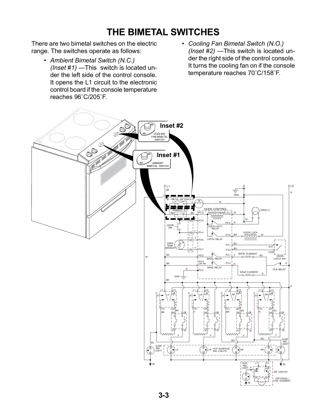
There are two bimetal switches on the electric range. The switches operate as follows:
•Ambient Bimetal Switch (N.C.)
(Inset #1)
•Cooling Fan Bimetal Switch (N.O.) (Inset #2)
Inset #2
COOLING
FAN BIMETAL
SWITCH
Inset #1
AMBIENT
BIMETAL SWITCH
L1 |
|
|
| L2 |
BK |
|
|
| R |
|
|
| GND | |
|
|
|
| |
BI - METAL SW FAN N.O. | M |
|
| |
Y | Y | W |
| |
|
| |||
|
| OVEN CONTROL | OVEN LT. | |
AMBIENT N.C. |
|
| ||
| ||||
BK | BK |
| ||
Y | |
|
W
| DOOR |
|
|
| OVEN LIGHT |
|
|
|
|
|
|
|
| |
| SW. |
|
|
|
|
|
|
|
|
|
|
| ||
|
|
|
|
| RELAY |
|
|
|
|
|
|
|
| |
|
|
| Y |
|
|
|
|
|
|
|
|
|
| |
|
|
|
|
|
|
|
| DOOR LOCK |
|
|
| |||
|
|
|
|
|
|
| BR | W |
|
| ||||
|
|
|
|
|
|
| SOLENOID |
|
| |||||
|
|
| V | LATCH RELAY |
|
|
|
|
|
|
|
| ||
|
|
|
|
|
|
|
|
|
|
|
| |||
| OVEN |
|
|
|
|
| BU |
|
|
|
|
| ||
| TEMP |
|
|
|
|
|
|
|
|
|
| N.O. | ||
| SENSOR |
| V |
|
|
| BU |
|
|
| ||||
|
|
|
|
|
|
|
|
| ||||||
|
|
|
|
|
|
|
|
|
|
| COM | |||
|
|
|
|
|
|
|
|
| BROIL ELEMENT |
| ||||
| BK |
|
|
|
| V | BU |
| DOOR | |||||
W |
|
|
|
|
|
|
|
| ||||||
|
|
|
| BROIL RELAY |
|
|
|
|
|
|
| |||
|
|
|
|
|
|
|
|
|
|
| LATCH SW. | |||
|
|
|
|
|
|
|
|
|
|
| ||||
| BK |
|
|
|
|
|
|
|
|
|
| R | ||
|
|
| OR P6 |
| R |
|
|
|
|
| ||||
|
| G |
| BAKE RELAY |
|
|
|
|
|
|
| DLB RELAY | ||
|
|
|
|
|
|
|
| BAKE ELEMENT |
|
| ||||
|
|
|
|
|
|
|
|
|
| R |
|
| ||
|
|
|
|
|
|
|
|
|
|
|
|
|
| |
| GND |
|
|
|
|
|
|
|
|
|
|
|
|
|
| BK |
|
|
|
|
|
|
|
|
|
|
|
|
|
|
|
|
|
|
|
|
|
|
|
|
|
|
| R |
L1 | L2 |
| L1 |
| L2 |
| L1 |
| L2 |
| L1 | L2 | ||
P | LF | P |
| LR |
| P |
| RF |
|
| P | RR |
|
|
|
|
|
|
|
|
|
|
|
|
| ||||
H1 | H2 BK | 2B | H1 |
| H2 Y | 2B | H1 |
| H2 | BR |
| H1 | H2 | BU |
BK | 2A | Y |
| 2A | BR |
| 2A | 2B |
| R | 2A | 2B | ||
| 1A | 1B |
| 1A | 1B |
|
| 1A | 1B |
|
| 1A | 1B | |
| V |
|
|
| V |
|
|
|
| V |
|
|
| V |
|
|
|
|
|
|
|
| BU |
|
|
| BU |
| SURF |
BU |
|
|
|
|
|
|
|
|
|
|
|
| IND. | |
|
|
|
|
|
|
|
|
|
|
|
|
| ||
|
|
|
|
|
|
|
|
|
|
|
|
| LIGHT | |
SURF |
|
|
|
|
|
|
|
|
|
|
|
|
| |
|
|
|
|
|
|
|
|
|
|
|
|
|
| |
IND. | LF |
|
|
| LR | HOT SURFACE |
|
| RF |
| RR |
|
| |
LIGHT |
|
|
| IND. LIGHTS |
|
|
|
|
| |||||
N |
|
|
|
|
|
|
|
|
| SUR. | L1 | L2 | N | |
|
|
|
|
|
|
|
|
| IND. |
|
|
| ||
|
|
|
|
|
|
|
|
|
|
|
|
|
| |
|
|
|
|
|
|
|
|
|
| LIGHT P |
|
|
|
|
|
|
|
|
|
|
|
|
|
|
|
|
|
| INF. SWITCH |
|
|
|
|
|
|
|
|
|
|
| H1 | H2 |
| (OPTIONAL) |
|
|
|
|
|
|
|
|
|
| N |
|
|
| COIL ELEMENT |
|
|
|
|
|
|
|
|
|
|
|
|
|
| |
