![]() WARNING
WARNING
Electrical Shock Hazard
Disconnect power before servicing.
Replace all parts and panels before operating.
Failure to do so can result in death or electrical shock.
DUAL ELEMENT INFINITE SWITCH (OPTIONAL)
P1
2
4
P2
S1
1.Unplug range or disconnect power.
2.Set the ohmmeter to the R X 1 scale.
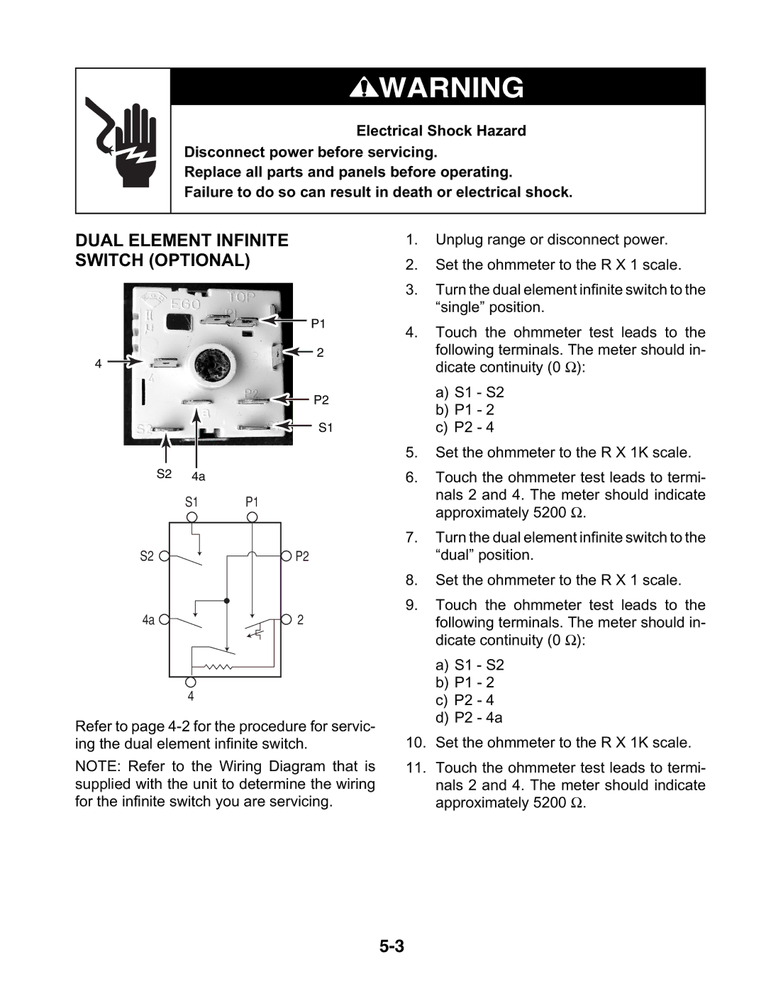
3.Turn the dual element infinite switch to the “single” position.
4.Touch the ohmmeter test leads to the
following terminals. The meter should in- dicate continuity (0 Ω):
a)S1 - S2
b)P1 - 2
c)P2 - 4
5.Set the ohmmeter to the R X 1K scale.
S2 | 4a |
|
| S1 | P1 |
S2 |
| P2 |
4a |
| 2 |
| 4 |
|
Refer to page
NOTE: Refer to the Wiring Diagram that is supplied with the unit to determine the wiring for the infinite switch you are servicing.
6.Touch the ohmmeter test leads to termi-
nals 2 and 4. The meter should indicate approximately 5200 Ω.
7.Turn the dual element infinite switch to the “dual” position.
8.Set the ohmmeter to the R X 1 scale.
9.Touch the ohmmeter test leads to the
following terminals. The meter should in- dicate continuity (0 Ω):
a)S1 - S2
b)P1 - 2
c)P2 - 4
d)P2 - 4a
10.Set the ohmmeter to the R X 1K scale.
11.Touch the ohmmeter test leads to termi-
nals 2 and 4. The meter should indicate approximately 5200 Ω.
