COOLING FAN AIR FLOW
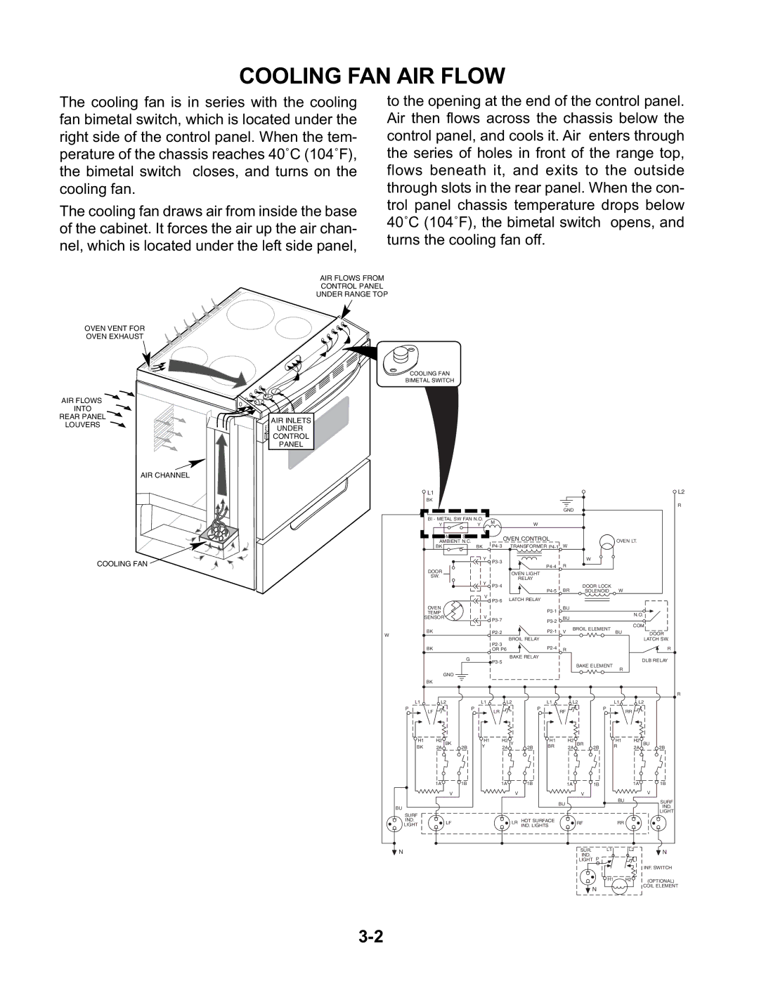
The cooling fan is in series with the cooling fan bimetal switch, which is located under the right side of the control panel. When the tem- perature of the chassis reaches 40˚C (104˚F), the bimetal switch closes, and turns on the cooling fan.
The cooling fan draws air from inside the base of the cabinet. It forces the air up the air chan- nel, which is located under the left side panel,
to the opening at the end of the control panel. Air then flows across the chassis below the control panel, and cools it. Air enters through the series of holes in front of the range top, flows beneath it, and exits to the outside through slots in the rear panel. When the con- trol panel chassis temperature drops below 40˚C (104˚F), the bimetal switch opens, and turns the cooling fan off.
OVEN VENT FOR
OVEN EXHAUST
AIR FLOWS
INTO
REAR PANEL
LOUVERS
AIR CHANNEL
COOLING FAN
AIR FLOWS FROM
CONTROL PANEL
UNDER RANGE TOP
COOLING FAN
BIMETAL SWITCH
AIR INLETS

 UNDER
UNDER
CONTROL
PANEL
| L1 |
|
|
|
|
|
|
|
|
|
|
|
| L2 |
| BK |
|
|
|
|
|
|
|
|
|
|
|
| R |
|
|
|
|
|
|
|
| GND |
|
|
|
| ||
|
|
|
|
|
|
|
|
|
|
|
|
| ||
| BI - METAL SW FAN N.O. | M |
|
|
|
|
|
|
|
|
|
| ||
| Y |
| Y |
| W |
|
|
|
|
|
|
|
| |
|
|
|
|
|
|
|
|
|
|
|
| |||
|
|
| OVEN CONTROL |
|
|
|
| OVEN LT. |
| |||||
| AMBIENT N.C. |
|
|
|
|
|
|
| ||||||
| BK | TRANSFORMER | W |
|
|
|
| |||||||
| BK |
|
|
|
|
|
|
| ||||||
|
|
| Y |
|
|
|
|
| W |
|
|
|
| |
|
|
|
|
|
| R |
|
|
|
|
|
| ||
| DOOR |
|
|
|
|
|
|
|
|
|
|
| ||
|
|
|
| OVEN LIGHT |
|
|
|
|
|
|
|
| ||
| SW. |
|
|
|
|
|
|
|
|
|
|
| ||
|
|
|
|
| RELAY |
|
|
|
|
|
|
|
| |
|
|
| Y |
|
|
|
|
|
|
|
|
|
| |
|
|
|
|
|
|
|
| DOOR LOCK |
|
|
| |||
|
|
|
|
|
|
| BR |
| W |
|
| |||
|
|
|
|
|
|
|
| SOLENOID |
|
| ||||
|
|
| V | LATCH RELAY |
|
|
|
|
|
|
|
| ||
|
|
|
|
|
|
|
|
|
|
|
| |||
| OVEN |
|
|
|
|
| BU |
|
|
|
|
|
| |
| TEMP |
|
|
|
|
|
|
|
|
|
| N.O. | ||
| SENSOR |
| V |
|
|
| BU |
|
|
|
| |||
|
|
|
|
|
|
|
|
|
| |||||
|
|
|
|
|
|
|
|
|
|
| COM | |||
|
|
|
|
|
|
|
|
| BROIL ELEMENT |
| ||||
| BK |
|
|
|
| V | BU |
| DOOR | |||||
W |
|
|
|
|
|
|
|
| ||||||
|
|
|
| BROIL RELAY |
|
|
|
|
|
|
| |||
|
|
|
|
|
|
|
|
|
|
| LATCH SW. | |||
|
|
|
|
|
|
|
|
|
|
| ||||
| BK |
|
|
|
|
|
|
|
|
|
| R | ||
|
|
| OR P6 |
| R |
|
|
|
|
| ||||
|
| G |
| BAKE RELAY |
|
|
|
|
|
|
| DLB RELAY | ||
|
|
|
|
|
|
|
| BAKE ELEMENT |
|
| ||||
|
|
|
|
|
|
|
|
|
| R |
|
| ||
|
|
|
|
|
|
|
|
|
|
|
|
|
| |
| GND |
|
|
|
|
|
|
|
|
|
|
|
|
|
| BK |
|
|
|
|
|
|
|
|
|
|
|
|
|
|
|
|
|
|
|
|
|
|
|
|
|
|
| R |
L1 | L2 |
| L1 |
| L2 |
| L1 |
| L2 |
| L1 | L2 | ||
P | LF | P |
| LR |
| P |
| RF |
|
| P | RR |
|
|
|
|
|
|
|
|
|
|
|
|
| ||||
H1 | H2 BK | 2B | H1 |
| H2 Y | 2B | H1 | H2 | BR |
| H1 | H2 | BU | |
BK | 2A | Y |
| 2A | BR | 2A | 2B |
| R | 2A | 2B | |||
| 1A | 1B |
| 1A | 1B |
| 1A | 1B |
|
| 1A | 1B | ||
| V |
|
|
| V |
|
|
|
| V |
|
|
| V |
|
|
|
|
|
|
| BU |
|
|
| BU |
| SURF | |
BU |
|
|
|
|
|
|
|
|
|
|
| IND. | ||
|
|
|
|
|
|
|
|
|
|
|
|
| ||
|
|
|
|
|
|
|
|
|
|
|
|
| LIGHT | |
SURF |
|
|
|
|
|
|
|
|
|
|
|
|
| |
|
|
|
|
|
|
|
|
|
|
|
|
|
| |
IND. | LF |
|
|
| LR | HOT SURFACE |
|
| RF |
| RR |
|
| |
LIGHT |
|
|
| IND. LIGHTS |
|
|
|
|
| |||||
N |
|
|
|
|
|
|
|
|
| SUR. | L1 | L2 | N | |
|
|
|
|
|
|
|
|
| IND. |
|
|
| ||
|
|
|
|
|
|
|
|
|
| LIGHT P |
|
|
|
|
|
|
|
|
|
|
|
|
|
|
|
|
|
| INF. SWITCH |
|
|
|
|
|
|
|
|
|
|
| H1 | H2 |
| (OPTIONAL) |
|
|
|
|
|
|
|
|
|
| N |
|
|
| COIL ELEMENT |
|
|
|
|
|
|
|
|
|
|
|
|
|
| |