Leica DM IRB
Tel. +49
Leica DM IRB
Copyrights
Contents
Operation
Automatic lowering
Important notes on this manual
Text symbols and their meaning
→ p
General safety information
Mains plug must only be inserted into a grounded outlet
Page
Intended application
Microscope and its components
Key subassemblies
Tube mount
Stand
First of all, here is a general overview Stands
Tube
Condenser height adjustment
Brightness adjustment
Mains switch
Coarse and fine control
Objective nosepiece and objectives
Specimen stages and accessories
Lamphousings
IR/R tube adapter
Installation site
Ambient conditions Temperature 10 36 C Relative humidity
Unpacking Installation
Assembly tools
Assembly
Assembly of the transmitted light illumination column
Assembly of condensers
Transmitted light illumination column, back view
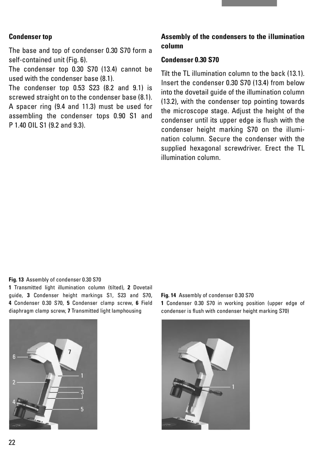
Condenser 0.30 S70
Position condenser disc, empty
Assembly of IC condenser prisms
Condenser 0.90 S1 bottom up
Assembly of condenser 0.30 S70
Condenser top
Assembly of condenser holder
Condensers 0.53 S23 and 0.90 S1
Assembly of field diaphragm
Assembly of filters and filter holder
Examples of prisms
Retrofitting individual IC prisms
Prism a for objectives N Plan 5x
Inserting the analyser
Differences between prism D and D1
Inserting the polariser
Inserting the fluorescence module
Fluorescence module
Connect the lamp plug to the connecting socket in the stand
Mirror housing and illumination telescope
Lamphousing 107 L
Assembling and exchanging incident light lamps
Lamphousing 106 z L
Lamphousing 106 z L
Power units
Type
It is extremely important to heed the follow- ing advice
Assembly of the tubes and tube adapter IR/R
Bino HC BSA 25 Trino HC FSA 25 P and PR
+ PR = with and without back reflection
Tube adapter R/IR HC, 2 Clamp screw Adapter, 6 Photo/TV port
Transformer Edge of the mirror housing, 11 Mirror housing
Inserting graticules
Inserting the eyepieces
Screw the retainer ring back
Screwing objectives in and out
Inserting the photoeyepieces
Remove the screw covers from the objective threads
Plate x/y stage
Only press the spring at the side
Connecting the microscope to the mains
Rotary stage and insert frame for coverslips
Important note
E version DM IRB/E Features of the Leica DM IRB/E
Function and operation
Assembly and initial installation
Controls
Installing the objective prisms
Learn mode
Exit option in the display flashes
Installing the objectives
I T
Display Objective magnification
Display Phase contrast
Display IC objective prism
Immersion objectives
Operating modes Dry/Immersion
To learn further objectives
Dry objectives
Exiting the Learn mode
Parfocality
Oil immersion objectives
Individual user adjustments
Sw i t c he s
Concluding the installation
Installing the fluorescence filter cube
With the key, → b
Motorized objective nosepiece
DRY and Immersion
Changing the operating mode
Operating modes
Now appears in the LC display at the bottom right
Automatic lowering of the objective nosepiece
Brightness adjustment
Electronic focus
Controls of the electronic focus are
Coded IC objective prisms option
Latter flashes if the combination is wrong
Motorised fluorescence filter cube change option
Connecting the control unit
Control unit
Keys on the control unit
Component Name on the unit
Lamp
Focus
Examples for the use of the footswitches
Switch position Sensor OFF
Switch position Auto
Switch position Light on
Person sensor option
86mm S 10 0 xPH3 HH
Front controls
Operation Basic setting
Switching on the halogen lamp
Adjustment specimen
Focusing the specimen
Setting the tubes and eyepieces
Operation of L objectives with correction mount
Only when one eyepiece is without an adjustable eyelens
Trinocular tube HCI 3T22
Side of the tube
Operation of the side photo/TV port
Operation of the front photo/TV port
Colour coding of objectives
Operation of objectives
Immersion objectives
Locking objectives
Page
Setting Koehler illumination
Fig.Ê 62Ê Ê
Possible errors
Replace the eyepiece or disengage the Bertrand lens
Operation of phase contrast
Phase contrast observation
Setting phase contrast with condensers 0.53 S23 and 0.90 S1
Operation of transmitted light darkfield
Darkfield observation
DL polarisation
Crossing the polarisers
Operation Transmitted light interference contrast
TL interference contrast
Centration of the condenser prisms
Objectives for ICT
Sources of error if ICT image quality is unsatisfactory
Setting ICT contrast
Choice of prisms
Operation of incident light fluorescence
Fluorescence observation
Method Centration with a centring aid
Alternative centration methods
Method Centration in the rear focal plane of the objective
Method
Lamphousing 106 z L with halogen lamp, Xe and Hg lamps
Centration of 12 V 100 W halogen lamp
Hg 50 W mercury lamp
Hg 100 W and Xe 75 W lamps
Halogen lamp Hg 50 lamp Xe 75 lamp
Centring the aperture diaphragm
Centring the field diaphragm
Weak fluorescence, insufficient brightness
Glass surfaces dirty
Operation of filters
Light filters
Slides with the following line patterns are available
Operation of the slide overlay device
Slide overlay device
Scale 10 mm = 100 divisions
Operation of the macro device
Fig.Ê 73ÊMacroÊ device on FSA 25 PE tube with tube adapter
Field of view Ø 10x/20 eyepiece
Total magnification in the eyepiece would therefore be
Transmitted light stage micrometer for cali- bration
Length measurements
Following components are required for length measurements
Calibration
With zoom magnification Vario TV adapter
MTV = objective magnification x tube factor Monitor diameter
Long-term video microscopy
Fig.Ê 80ÊLeicaÊ DM IRB, equipped with three TV cameras
Operation of LMC
Principle of LMC
Principle
LMC consists of the following components
Components
Components
S40/0.50 LMC condenser
Adjustment
Assembly/adjustment
Assembly
Screw the LMC objectives into the objective nosepiece
Page
Areas of application
Care and maintenance
Acids, alkaline solutions
Cleaning objectives
Removal of immersion oil
Electric errors
Troubleshooting
Mechanical errors
On/off switch does not respond no illumination
Additional fluorescence lamp does not respond
106
Schutter FST
846-205.000-00
Name
107
Ê Lamphousing 106 z, opened
108
Replacing the 12 V 100 W halogen lamp in lamphousing 106 z
109
Changing the Hg and Xe lamps on lamphousing 106 z
111
Storage
Transport
Objective lettering
Technical description
Performance data of objectives
0Ê -Ê
10x/0.22
Or A, B, C
Objective type performance class Plan
114
White Water
Colour coding of the objectives
Locking of objectives
Decisive value is always the smallest
Performance data of eyepieces
Eyepiece field of view
Field performance of objectives
Eyepiece graticules
BG20
Filter performance data Use Grey/neutral density filter N
Green filter, GR, panchromatic
CB1.5, CB3
Binocular ergotube HCI BV22
Tube performance data
Binocular tube HCI B22
Like HCI B22, but with variable viewing angle of 15Ê -Ê
Trinocular tube HCI 3T22
Tube adapter R/IR
Condenser performance data Condenser 0.30 S70
121
Object guide
Condenser disc
122
Lamphousing 107/2
Lamphousing performance data
Lamphousing 106 z
Stages Plane stage and mountable object guide
Xe high pressure lamp 75 W D.C., stabilised
Type
Hg ultra high pressure lamp 50 W A.C
C., stabilised/non-stabilised
Fuses Ambient temperature 10Ê -Ê 36C Relative humidity
General technical data
General technical data
Overvoltage category Contamination class 125
Technical specifications
Technical data of the power unit General technical data
ULa = lamp voltage
Main wearing and spare parts, tools
127
EU Conformity declaration
Product name
Page
Ernst-Leitz-Straße