|
| The Algorithms and Their Parameters |
Mod: Sw 1 and Mod: Sw 2 | Modulation cont'd. | |
These are identical time switches. Each has five parameters: Rate, P Width, |
| |
Mode, T Lvl and T Src. |
| |
Rate | sets the speed at which the switch cycles. It can be set in |
|
| time values (such as 1.5 Hz) or tempo values (such as 3:2 |
|
| Cycles per Beat). Simultaneously pressing Up and |
|
| Tempo will toggle these display options. |
|
P Width | determines the proportion of each switch cycle during |
|
| which the switch is on. For example, setting P Width to |
|
| 50% means that the switch is on for |
|
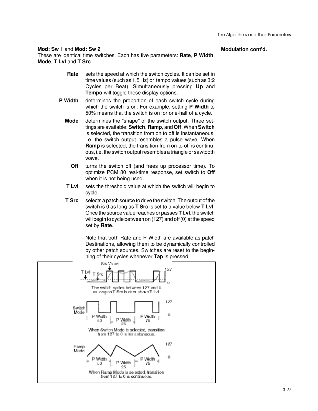
Mode | determines the “shape” of the switch output. Three set- | |
| tings are available: Switch, Ramp, and Off. When Switch |
|
| is selected, the transition from on to off is instantaneous, |
|
| i.e. the switch output resembles a pulse wave. When |
|
| Ramp is selected, the transition from on to off is continu- |
|
| ous, i.e. the switch output resembles a triangle or sawtooth |
|
| wave. |
|
Off | turns the switch off (and frees up processor time). To |
|
| optimize PCM 80 |
|
| when it is not being used. |
|
T Lvl | sets the threshold value at which the switch will begin to |
|
| cycle. |
|