Power and Control Wiring
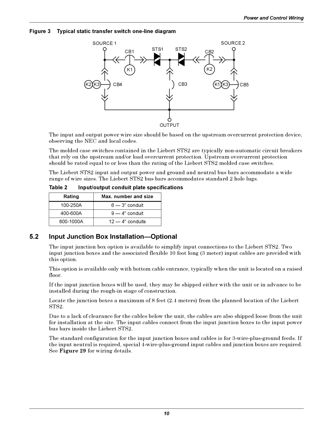
Figure 3 Typical static transfer switch one-line diagram
SOURCE 1
CB1 STS1
K1
K2 K3 ![]() CB4
CB4
SOURCE 2
STS2 | CB2 |
|
|
| |
| K2 |
|
CB3 | K1 K3 | CB5 |
OUTPUT
The input and output power wire size should be based on the upstream overcurrent protection device, observing the NEC and local codes.
The molded case switches contained in the Liebert STS2 are typically
The Liebert STS2 input and output power and ground and neutral bus bars accommodate a wide range of wire sizes. The Liebert STS2 bus bars accommodates standard 2 hole lugs.
Table 2 | Input/output conduit plate specifications | |||
|
|
| ||
Rating | Max. number and size |
| ||
|
|
|
| |
6 | — 3" conduit |
| ||
|
|
|
| |
9 | — 4" conduit |
| ||
|
|
|
| |
12 | — 4" conduits |
| ||
|
|
|
|
|
5.2Input Junction Box Installation—Optional
The input junction box option is available to simplify input connections to the Liebert STS2. Two input junction boxes and the associated flexible 10 foot long (3 meter) input cables are provided with this option.
This option is available only with bottom cable entrance, typically when the unit is located on a raised floor.
If the input junction boxes will be used, they may be shipped either with the unit or in advance to be installed during the
Locate the junction boxes a maximum of 8 feet (2.4 meters) from the planned location of the Liebert STS2.
Due to a lack of clearance for the cables below the unit, the cables are also shipped loose from the unit for installation at the site. The input cables connect from the input junction boxes to the input power bus bars inside the Liebert STS2.
The standard configuration for the input junction boxes and cables is for
10