Liebert STS2 Touch Screen Display
To configure your programmable relay boards for user defined settings:
1.Select PROG. RELAY BOARD # x from the Comm Options dialog box, where x is the corresponding board number.
The Prog. Relay Board dialog box is displayed.
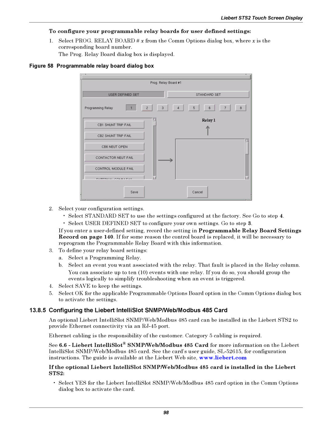
Figure 58 Programmable relay board dialog box
2.Select your configuration settings.
•Select STANDARD SET to use the settings configured at the factory. See Go to step 4.
•Select USER DEFINED SET to configure your own settings. Go to step 3.
If you enter a
3.To define your relay board settings:
a.Select a Programming Relay.
b.Select an event you want associated with the relay. That fault is placed in the Relay column.
You can associate up to ten (10) events with one relay. If you do so, you should group the events logically to simplify troubleshooting when an event is triggered.
4.Select SAVE to keep the settings.
5.Select OK for the applicable Programmable Options Board option in the Comm Options dialog box to activate the settings.
13.8.5Configuring the Liebert IntelliSlot SNMP/Web/Modbus 485 Card
An optional Liebert IntelliSlot SNMP/Web/Modbus 485 card can be installed in the Liebert STS2 to provide Ethernet connectivity via an
Ethernet cabling is the responsibility of the customer. Category 5 cabling is required.
See 6.6 - Liebert IntelliSlot® SNMP/Web/Modbus 485 Card for more information on the Liebert IntelliSlot SNMP/Web/Modbus 485 card. See the card’s user guide,
If the optional Liebert IntelliSlot SNMP/Web/Modbus 485 card is installed in the Liebert STS2:
•Select YES for the Liebert IntelliSlot SNMP/Web/Modbus 485 card option in the Comm Options dialog box to activate the card.
98