Installation Drawings
7.0INSTALLATION DRAWINGS
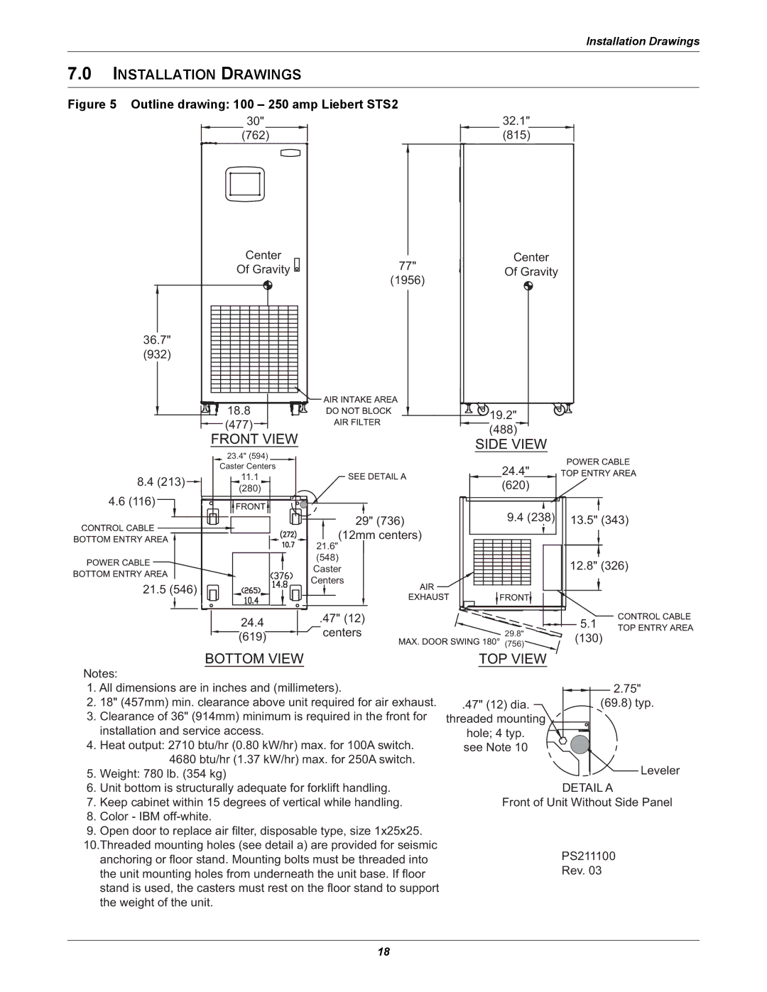
Figure 5 Outline drawing: 100 – 250 amp Liebert STS2 | 32.1" |
| ||
| 30" |
|
| |
| (762) |
| (815) |
|
| Center | 77" | Center |
|
| Of Gravity | Of Gravity |
| |
|
| (1956) |
|
|
36.7" |
|
|
|
|
(932) |
|
|
|
|
| 18.8 |
| 19.2" |
|
| (477) |
|
| |
|
| (488) |
| |
|
|
|
| |
| 23.4" (594) |
|
|
|
| Caster Centers |
| 24.4" |
|
8.4 (213) | 11.1 |
|
| |
| (620) |
| ||
(280) |
|
| ||
4.6 (116) |
|
|
|
|
|
| 29" (736) | 9.4 (238) | 13.5" (343) |
|
| (12mm centers) |
|
|
|
| 21.6" |
|
|
|
| (548) |
| 12.8" (326) |
|
| Caster |
| |
21.5 (546) |
| Centers |
|
|
|
|
|
| |
| 24.4 | .47" (12) |
| 5.1 |
| centers | 29.8" | ||
| (619) | (130) | ||
|
| (756) | ||
|
|
|
| |
Notes: |
|
|
|
|
1. All dimensions are in inches and (millimeters). |
| 2.75" | ||
2. 18" (457mm) min. clearance above unit required for air exhaust. | .47" (12) dia. | (69.8) typ. | ||
3. Clearance of 36" (914mm) minimum is required in the front for | threaded mounting |
| ||
installation and service access. |
| hole; 4 typ. |
| |
4. Heat output: 2710 btu/hr (0.80 kW/hr) max. for 100A switch. | see Note 10 |
| ||
4680 btu/hr (1.37 kW/hr) max. for 250A switch. |
| Leveler | ||
5. Weight: 780 lb. (354 kg) |
|
| ||
6. Unit bottom is structurally adequate for forklift handling. |
| DETAIL A | ||
7. Keep cabinet within 15 degrees of vertical while handling. | Front of Unit Without Side Panel | |||
8.Color - IBM
9.Open door to replace air filter, disposable type, size 1x25x25.
10.Threaded mounting holes (see detail a) are provided for seismic | PS211100 |
anchoring or floor stand. Mounting bolts must be threaded into | |
the unit mounting holes from underneath the unit base. If floor | Rev. 03 |
stand is used, the casters must rest on the floor stand to support |
|
the weight of the unit. |
|
18