Installation Drawings
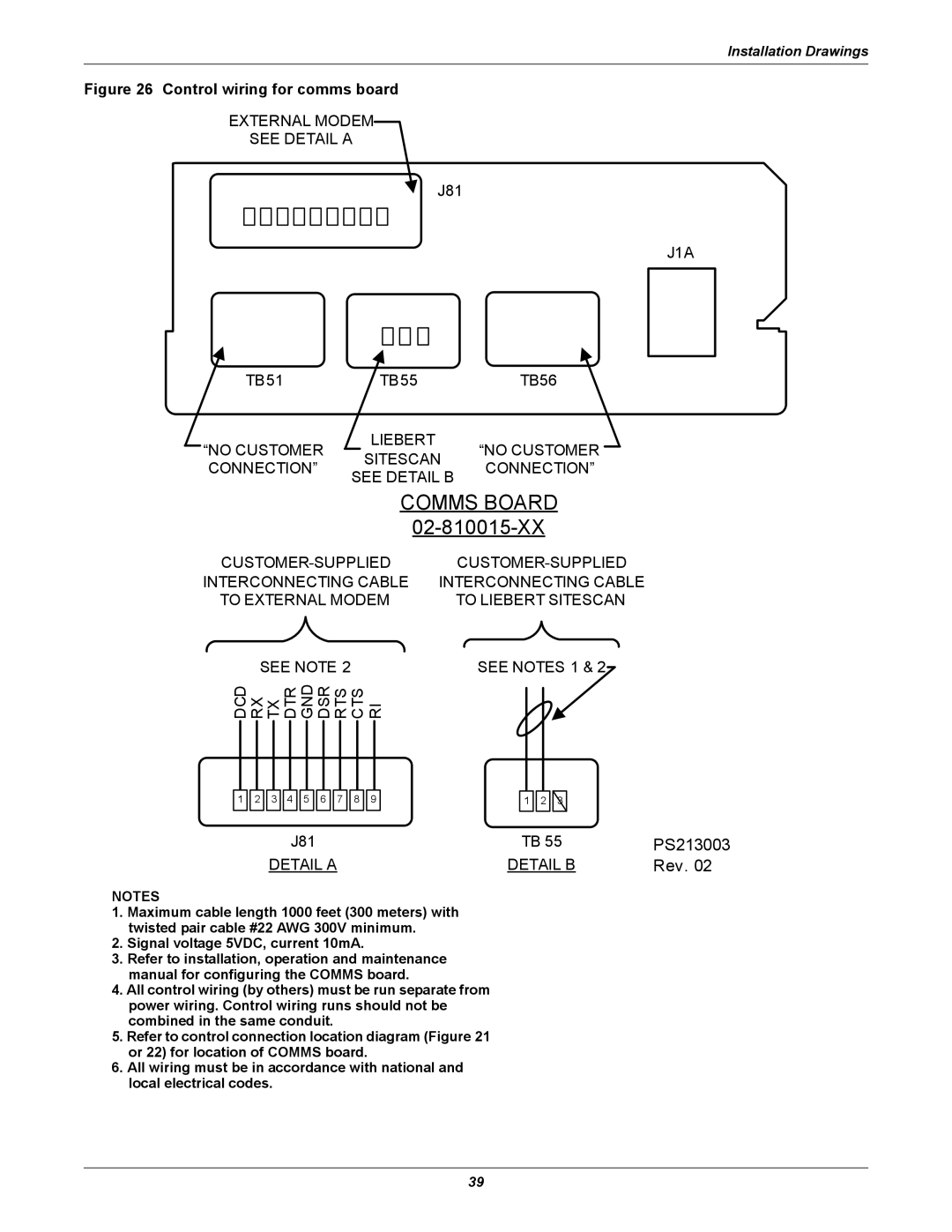
Figure 26 Control wiring for comms board
EXTERNAL MODEM
SEE DETAIL A
J81
J1A
TB51 |
| TB55 |
| TB56 | ||||
“NO CUSTOMER |
|
| LIEBERT |
| “NO CUSTOMER |
|
| |
|
| SITESCAN |
|
| ||||
CONNECTION” |
| CONNECTION” | ||||||
SEE DETAIL B | ||||||||
|
|
|
|
| ||||
|
|
| COMMS BOARD | |||||
|
|
|
| |||||
| ||||||||
INTERCONNECTING CABLE | INTERCONNECTING CABLE | |||||||
TO EXTERNAL MODEM |
| TO LIEBERT SITESCAN | ||||||
SEE NOTE 2 |
|
|
| SEE NOTES 1 & 2 | ||||
DCD RX TX DTR GND DSR RTS CTS RI |
|
|
|
| ||||
1 ![]()
![]() 2
2 ![]()
![]() 3
3 ![]()
![]() 4
4 ![]()
![]() 5
5 ![]()
![]() 6
6 ![]()
![]() 7
7 ![]()
![]() 8
8 ![]()
![]() 9
9
1 ![]()
![]() 2
2 ![]()
![]() 3
3
J81 | TB 55 | PS213003 |
DETAIL A | DETAIL B | Rev. 02 |
NOTES
1.Maximum cable length 1000 feet (300 meters) with twisted pair cable #22 AWG 300V minimum.
2.Signal voltage 5VDC, current 10mA.
3.Refer to installation, operation and maintenance manual for configuring the COMMS board.
4.All control wiring (by others) must be run separate from power wiring. Control wiring runs should not be combined in the same conduit.
5.Refer to control connection location diagram (Figure 21 or 22) for location of COMMS board.
6.All wiring must be in accordance with national and local electrical codes.
39