Operating the Liebert STS2 LED Display
14.1.2LED and Push Button Description
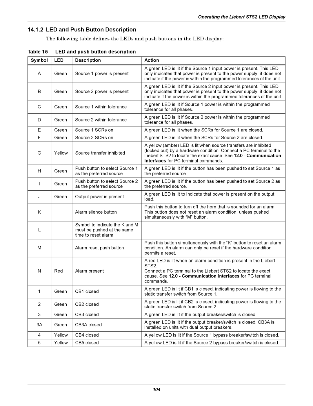
The following table defines the LEDs and push buttons in the LED display:
Table 15 LED and push button description
Symbol | LED | Description | Action | |
|
|
|
| |
|
|
| A green LED is lit if the Source 1 input power is present. This LED | |
A | Green | Source 1 power is present | only indicates that power is present to the power supply; it does not | |
|
|
| indicate if the power is within the programmed tolerances of the unit. | |
|
|
| A green LED is lit if the Source 2 input power is present. This LED | |
B | Green | Source 2 power is present | only indicates that power is present to the power supply; it does not | |
|
|
| indicate if the power is within the programmed tolerances of the unit. | |
C | Green | Source 1 within tolerance | A green LED is lit if Source 1 power is within the programmed | |
tolerance for all phases. | ||||
|
|
| ||
D | Green | Source 2 within tolerance | A green LED is lit if Source 2 power is within the programmed | |
tolerance for all phases. | ||||
|
|
| ||
E | Green | Source 1 SCRs on | A green LED is lit when the SCRs for Source 1 are closed. | |
|
|
|
| |
F | Green | Source 2 SCRs on | A green LED is lit when the SCRs for Source 2 are closed. | |
|
|
|
| |
|
|
| A yellow (amber) LED is lit when source transfers are inhibited | |
G | Yellow | Source transfer inhibited | (locked out) by a hardware condition. Connect a PC terminal to the | |
Liebert STS2 to locate the exact cause. See 12.0 - Communication | ||||
|
|
| ||
|
|
| Interfaces for PC terminal commands. | |
|
|
|
| |
H | Green | Push button to select Source 1 | A green LED is lit if the button has been pushed to set Source 1 as | |
as the preferred source | the preferred source. | |||
|
| |||
I | Green | Push button to select Source 2 | A green LED is lit if the button has been pushed to set Source 2 as | |
as the preferred source | the preferred source. | |||
|
| |||
J | Green | Output power is present | A green LED is lit to indicate that power is present on the output | |
load. | ||||
|
|
| ||
|
|
| Push this button to turn off the horn that is sounded for an alarm. | |
K |
| Alarm silence button | This button does not reset an alarm condition, unless pushed | |
|
|
| simultaneously with “M” button. | |
|
| Symbol to indicate the K and M |
| |
L |
| must be pushed at the same |
| |
|
| time to reset alarm |
| |
|
|
| Push this button simultaneously with the “K” button to reset an alarm | |
M |
| Alarm reset push button | condition. An alarm can only be reset if the hardware condition | |
|
|
| permits a reset. | |
|
|
| A red LED is lit when an alarm condition is present in the Liebert | |
|
|
| STS2. | |
N | Red | Alarm present | Connect a PC terminal to the Liebert STS2 to locate the exact | |
|
|
| cause. See 12.0 - Communication Interfaces for PC terminal | |
|
|
| commands. | |
1 | Green | CB1 closed | A green LED is lit if CB1 is closed, indicating power is flowing to the | |
static transfer switch from Source 1. | ||||
|
|
| ||
2 | Green | CB2 closed | A green LED is lit if CB2 is closed, indicating power is flowing to the | |
static transfer switch from Source 2. | ||||
|
|
| ||
3 | Green | CB3 closed | A green LED is lit if the output breaker/switch is closed. | |
|
|
|
| |
3A | Green | CB3A closed | A green LED is lit if the output breaker/switch is closed. CB3A is | |
installed on units with dual output breakers. | ||||
|
|
| ||
4 | Yellow | CB4 closed | A yellow LED is lit if the Source 1 bypass breaker/switch is closed. | |
|
|
|
| |
5 | Yellow | CB5 closed | A yellow LED is lit if the Source 2 bypass breaker/switch is closed. | |
|
|
|
|
104
