Options
6.0OPTIONS
This section discusses the options available for the Liebert STS2. The communications options are also discussed in 12.0 - Communication Interfaces.
6.1Programmable Relay Board
The Programmable Relay Board (PRB) provides a means to trigger an external device when an event occurs in the Liebert STS2. Each PRB has eight channels. Each channel has two sets of
Any alarm/event can be programmed to any channel or channels. Up to ten (10) events can be programmed to a relay. If multiple events are grouped to one relay, group the events logically to simplify troubleshooting when an event is triggered. The same alarm/event can be programmed to more than one channel. Up to two Programmable Relay Boards can be installed in the Liebert STS2 for a total of 16 channels. Programming is performed through the touch screen display.
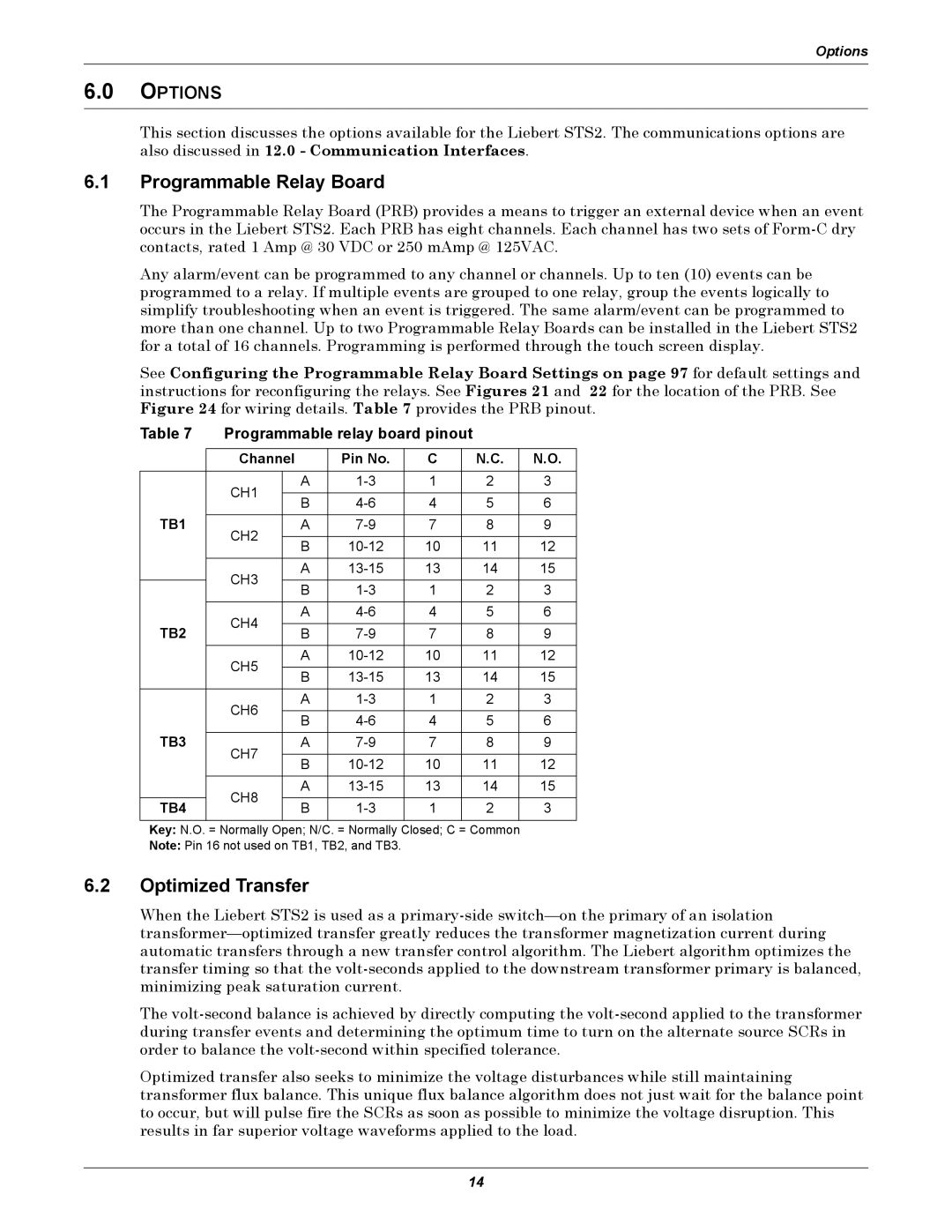
See Configuring the Programmable Relay Board Settings on page 97 for default settings and instructions for reconfiguring the relays. See Figures 21 and 22 for the location of the PRB. See Figure 24 for wiring details. Table 7 provides the PRB pinout.
Table 7 | Programmable relay board pinout |
|
| |||||
|
|
|
|
|
|
|
|
|
| Channel |
| Pin No. | C |
| N.C. | N.O. | |
|
|
|
|
|
|
|
|
|
| CH1 |
| A | 1 |
| 2 | 3 | |
|
|
|
|
|
|
|
| |
|
| B | 4 |
| 5 | 6 | ||
|
|
|
| |||||
TB1 |
|
|
|
|
|
|
|
|
CH2 |
| A | 7 |
| 8 | 9 | ||
|
|
|
|
|
|
|
| |
|
| B | 10 |
| 11 | 12 | ||
|
|
|
| |||||
|
|
|
|
|
|
|
|
|
| CH3 |
| A | 13 |
| 14 | 15 | |
|
|
|
|
|
|
|
| |
|
| B | 1 |
| 2 | 3 | ||
|
|
|
| |||||
|
|
|
|
|
|
|
|
|
| CH4 |
| A | 4 |
| 5 | 6 | |
TB2 |
|
|
|
|
|
|
| |
| B | 7 |
| 8 | 9 | |||
|
|
| ||||||
|
|
|
|
|
|
|
|
|
| CH5 |
| A | 10 |
| 11 | 12 | |
|
|
|
|
|
|
|
| |
|
| B | 13 |
| 14 | 15 | ||
|
|
|
| |||||
|
|
|
|
|
|
|
|
|
| CH6 |
| A | 1 |
| 2 | 3 | |
|
|
|
|
|
|
|
| |
|
| B | 4 |
| 5 | 6 | ||
|
|
|
| |||||
TB3 |
|
|
|
|
|
|
|
|
CH7 |
| A | 7 |
| 8 | 9 | ||
|
| B | 10 |
| 11 | 12 | ||
|
|
|
| |||||
|
|
|
|
|
|
|
|
|
| CH8 |
| A | 13 |
| 14 | 15 | |
|
|
|
|
|
|
|
| |
TB4 |
| B | 1 |
| 2 | 3 | ||
|
|
| ||||||
|
|
|
|
|
|
|
|
|
Key: N.O. = Normally Open; N/C. = Normally Closed; C = Common
Note: Pin 16 not used on TB1, TB2, and TB3.
6.2Optimized Transfer
When the Liebert STS2 is used as a
The
Optimized transfer also seeks to minimize the voltage disturbances while still maintaining transformer flux balance. This unique flux balance algorithm does not just wait for the balance point to occur, but will pulse fire the SCRs as soon as possible to minimize the voltage disruption. This results in far superior voltage waveforms applied to the load.
14