Installation Drawings
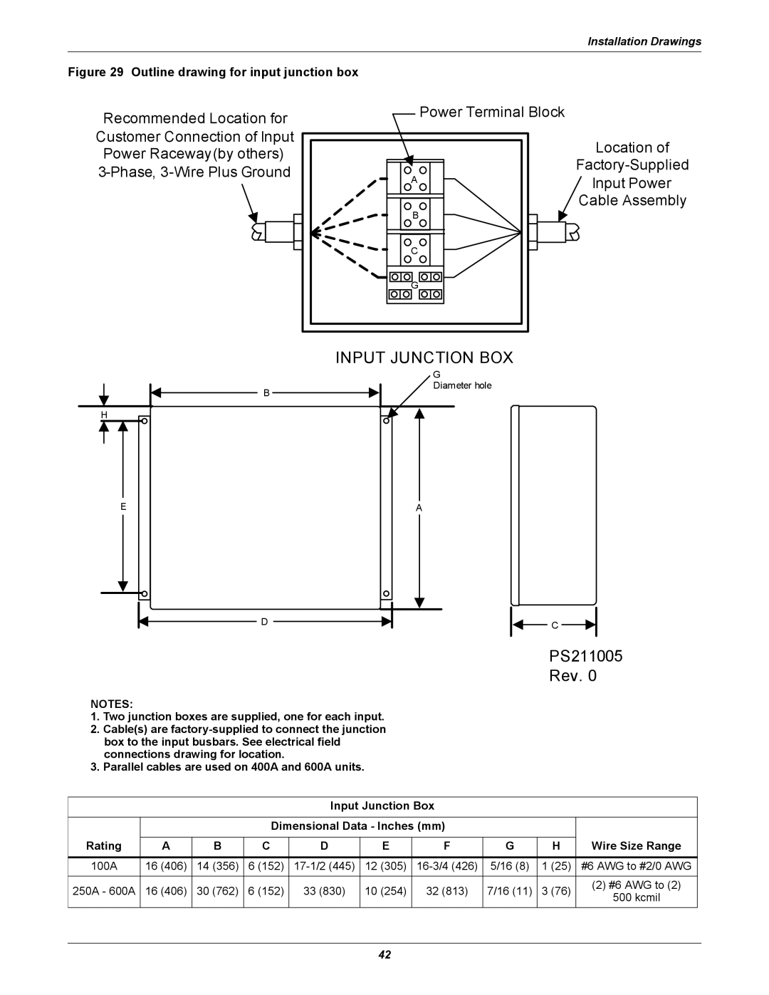
Figure 29 Outline drawing for input junction box
Recommended Location for Customer Connection of Input Power Raceway(by others)
Power Terminal Block
A |
B |
C |
G |
Location of
Input Power
Cable Assembly
INPUT JUNCTION BOX
B
H
G
Diameter hole
E | A |
D
NOTES:
1.Two junction boxes are supplied, one for each input.
2.Cable(s) are
3.Parallel cables are used on 400A and 600A units.
C
PS211005 Rev. 0
Input Junction Box
|
|
| Dimensional Data - Inches (mm) |
|
|
| ||||
Rating |
|
|
|
|
|
|
|
| Wire Size Range | |
A | B | C | D | E | F | G | H | |||
|
|
|
|
|
|
|
|
|
| |
100A | 16 (406) | 14 (356) | 6 (152) | 12 (305) | 5/16 (8) | 1 (25) | #6 AWG to #2/0 AWG | |||
|
|
|
|
|
|
|
|
|
| |
250A - 600A | 16 (406) | 30 (762) | 6 (152) | 33 (830) | 10 (254) | 32 (813) | 7/16 (11) | 3 (76) | (2) #6 AWG to (2) | |
500 kcmil | ||||||||||
|
|
|
|
|
|
|
|
| ||
42