INSTALLATION |
CABLE INDUCTANCE, AND ITS EFFECTS ON WELDING
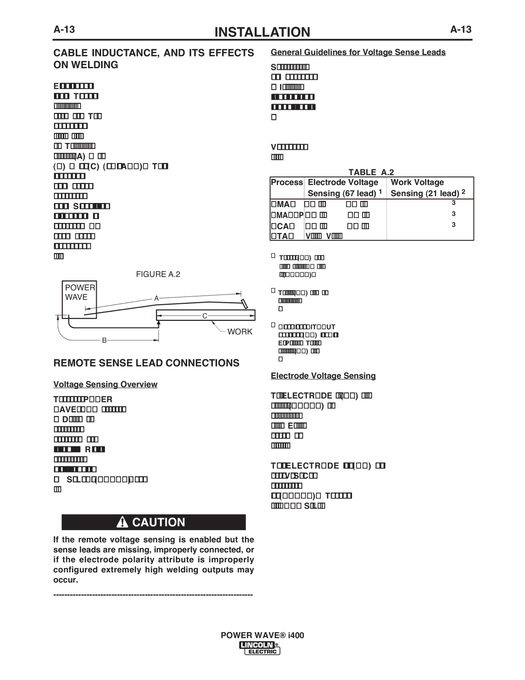
Excessive cable inductance will cause the welding performance to degrade. There are several factors that contribute to the overall inductance of the cabling system including cable size, and loop area. The loop area is defined by the separation distance between the electrode and work cables, and the overall welding loop length. The welding loop length is defined as the total of length of the electrode cable (A) + work cable
(B)+ work path (C) (see Figure A.2). To minimize inductance always use the appropriate size cables, and whenever possible, run the electrode and work cables in close proximity to one another to minimize the loop area. Since the most significant factor in cable inductance is the welding loop length, avoid excessive lengths and do not coil excess cable. For long work piece lengths, a sliding ground should be considered to keep the total welding loop length as short as possible.
POWER | FIGURE A.2 |
| |
WAVE | A |
| C |
| WORK |
| B |
REMOTE SENSE LEAD CONNECTIONS
Voltage Sensing Overview
The best arc performance occurs when the POWER WAVE® i400 has accurate data about the arc condi- tions. Depending upon the process, inductance within the electrode and work cables can influence the volt- age apparent at the studs of the welder, and have a dramatic effect on performance. Remote voltage sense leads are used to improve the accuracy of the arc voltage information supplied to the control pc board. Sense Lead Kits
![]() CAUTION
CAUTION
If the remote voltage sensing is enabled but the sense leads are missing, improperly connected, or if the electrode polarity attribute is improperly configured extremely high welding outputs may occur.
General Guidelines for Voltage Sense Leads
Sense leads should be attached as close to the weld as practical, and out of the weld current path when possible. In extremely sensitive applications it may be necessary to route cables that contain the sense leads away from the electrode and work welding cables.
Voltage sense leads requirements are based on the weld process as follows:
TABLE A.2
Process | Electrode Voltage | Work Voltage |
| Sensing (67 lead) 1 | Sensing (21 lead) 2 |
GMAW | 67 lead required | 21 lead optional 3 |
67 lead required | 21 lead optional 3 | |
FCAW | 67 lead required | 21 lead optional 3 |
GTAW | Voltage sense at studs | Voltage sense at studs |
1The electrode voltage sense lead (67) is automatically enabled by the weld process, and integral to the to the 14 pin wire feeder control cable (K1785).
2The work voltage sense lead (21) is manually enabled, but over- ridden by constant current weld processes defined for stud sens- ing.
3Negative polarity
Electrode Voltage Sensing
The remote ELECTRODE sense lead (67) is built into the standard wire feeder control cable (K1785) and is always connected to the wire drive feed plate when a wire feeder is present. Enabling or disabling electrode voltage sensing is application specific, and automati- cally configured by the active weld mode.
The remote ELECTRODE sense lead (67) is also available in the remote Voltage Sense Connector for applications that do not use the standard wire feeder control cable (K1785). This can be easily accessed with the optional K940 Sense Lead kit.
POWER WAVE® i400