OPERATION |
INTERNAL CONTROLS
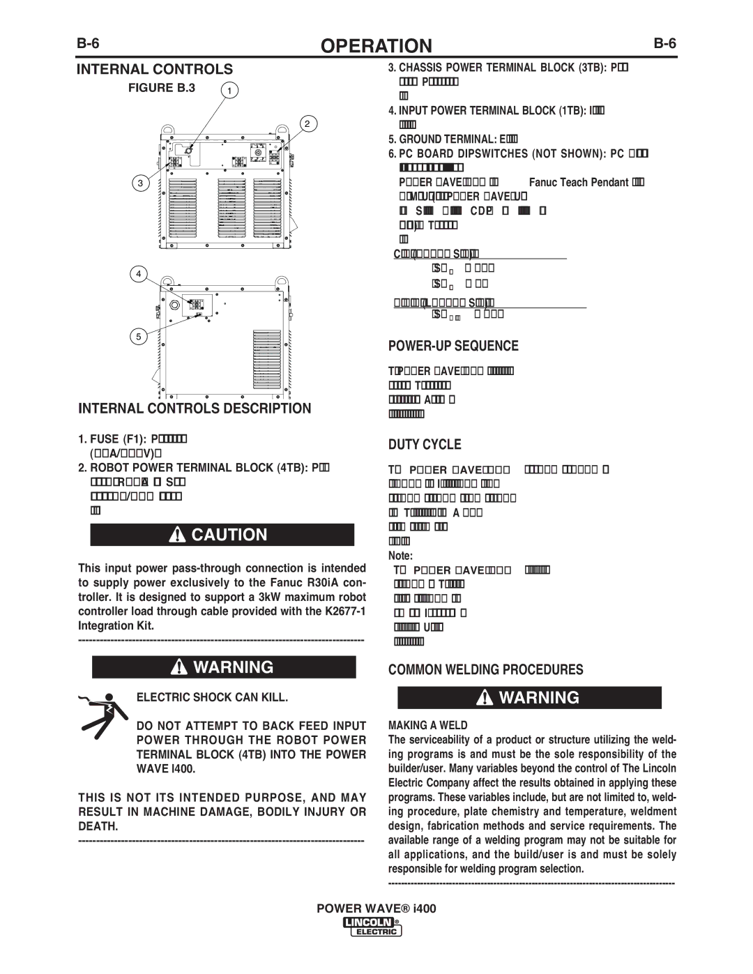
FIGURE B.3 | 1 |
2
3 |
4 |
5 |
INTERNAL CONTROLS DESCRIPTION
1.FUSE (F1): Primary circuit protection for auxiliary power (10A/600V).
2.ROBOT POWER TERMINAL BLOCK (4TB): Power sup- ply connection for Fanuc R30iA controller. Supplies pri- mary power through the ON/OFF switch directly to the robot controller.
![]() CAUTION
CAUTION
This input power
3.CHASSIS POWER TERMINAL BLOCK (3TB): Power connec- tion for internal chassis. Provides power for the inverter and all auxiliary supplies.
4.INPUT POWER TERMINAL BLOCK (1TB): Input power connec- tion from main service disconnect.
5.GROUND TERMINAL: Earth ground connection.
6.PC BOARD DIPSWITCHES (NOT SHOWN): PC Board dip- switches are set at the factory to allow configuration of the
POWER WAVE® i400 via the Fanuc Teach Pendant or with the Weld Manager Utility (included on the POWER WAVE® Utilities and Service Navigator CDʼs or available at www.powerwavesoftware.com). The factory default settings are as follows:
Control Board (G4800 Series Hardware):
•S1large = OFF
•S2small = ON
Feed Head Board (L11087 Series Hardware):
• S11 thru 8 = OFF
POWER-UP SEQUENCE
The POWER WAVE® i400 will typically be powered up at the same time as the robotic controller. The status lights will blink green for about a minute while the system is configuring. After this time, the status lights will turn a steady green indicating the machine is ready.
DUTY CYCLE
The POWER WAVE® i400 is rated at 350 amps at 31.5 volts with a 100% duty cycle. It is further rated to provide 400 amps at 34 volts with a 60% duty cycle and 420 amps at 35 volts with a 40% duty cycle. The duty cycle is based on a
Note:
The POWER WAVE® i400 is capable of producing a peak out- put current of 700 amps. The allowable maximum average output current is time dependent, but ultimately limited to 450 amps over any 2 second period. If the maximum average is exceeded, the output is disabled to protect the machine. Under these conditions, normal operation can be resumed by cycling the output command.
![]() WARNING
WARNING
ELECTRIC SHOCK CAN KILL.
DO NOT ATTEMPT TO BACK FEED INPUT POWER THROUGH THE ROBOT POWER TERMINAL BLOCK (4TB) INTO THE POWER WAVE I400.
THIS IS NOT ITS INTENDED PURPOSE, AND MAY RESULT IN MACHINE DAMAGE, BODILY INJURY OR DEATH.
COMMON WELDING PROCEDURES
![]() WARNING
WARNING
MAKING A WELD
The serviceability of a product or structure utilizing the weld- ing programs is and must be the sole responsibility of the builder/user. Many variables beyond the control of The Lincoln Electric Company affect the results obtained in applying these programs. These variables include, but are not limited to, weld- ing procedure, plate chemistry and temperature, weldment design, fabrication methods and service requirements. The available range of a welding program may not be suitable for all applications, and the build/user is and must be solely responsible for welding program selection.
POWER WAVE® i400