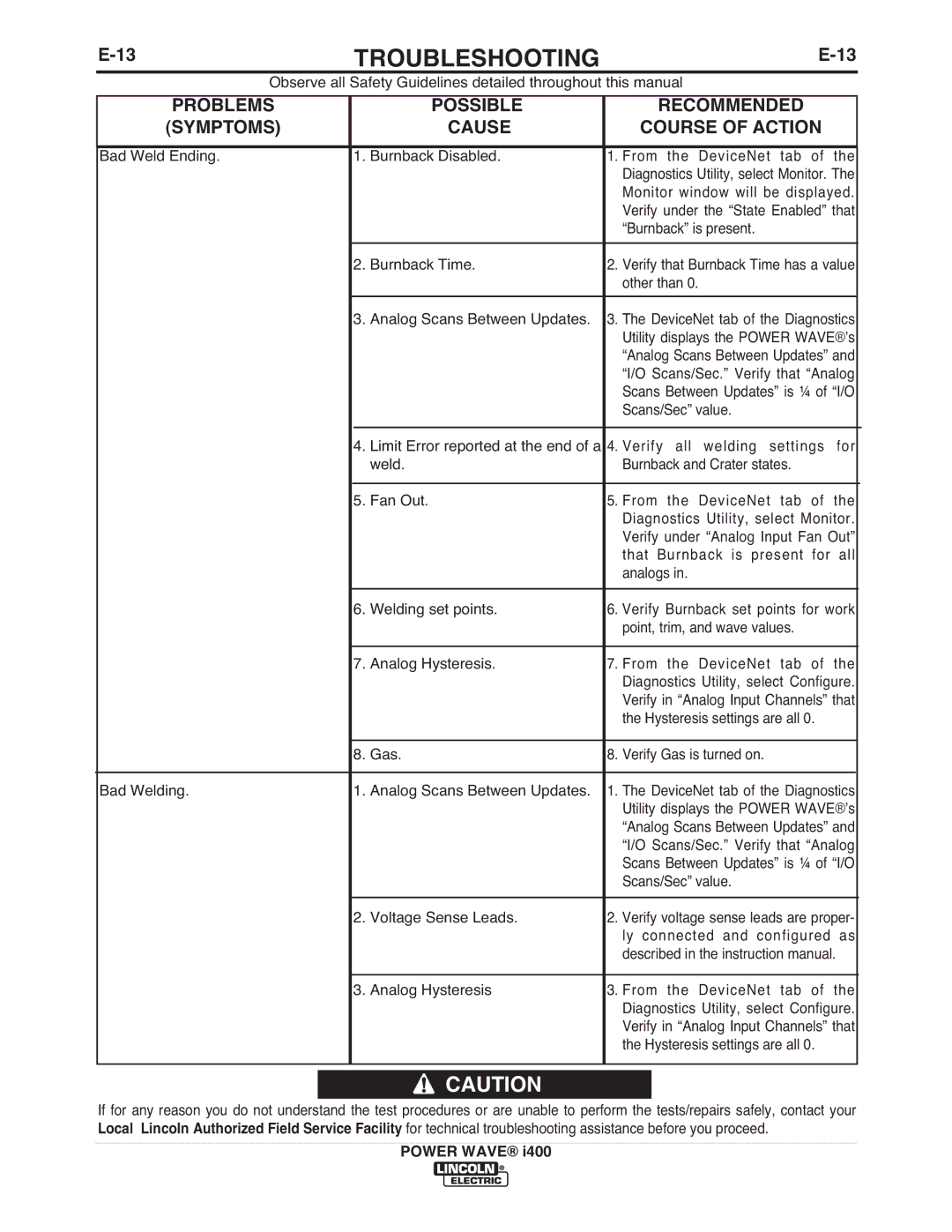
TROUBLESHOOTING | ||
| Observe all Safety Guidelines detailed throughout this manual |
|
PROBLEMS
(SYMPTOMS)
POSSIBLE
CAUSE
RECOMMENDED
COURSE OF ACTION
Bad Weld Ending. | 1. Burnback Disabled. | 1. From the DeviceNet tab of the |
| |||
|
|
|
|
| Diagnostics Utility, select Monitor. The |
|
|
|
|
|
| Monitor window will be displayed. |
|
|
|
|
|
| Verify under the “State Enabled” that |
|
|
|
|
|
| “Burnback” is present. |
|
| 2. | Burnback Time. | 2. | Verify that Burnback Time has a value |
| |
|
|
|
|
| other than 0. |
|
| 3. | Analog Scans Between Updates. | 3. | The DeviceNet tab of the Diagnostics |
| |
|
|
|
|
| Utility displays the POWER WAVE®ʼs |
|
|
|
|
|
| “Analog Scans Between Updates” and |
|
|
|
|
|
| “I/O Scans/Sec.” Verify that “Analog |
|
|
|
|
|
| Scans Between Updates” is ¼ of “I/O |
|
|
|
|
|
| Scans/Sec” value. |
|
|
|
|
|
|
|
|
| 4. | Limit Error reported at the end of a | 4. | Verify all welding settings for |
| |
|
|
| weld. |
| Burnback and Crater states. |
|
|
|
|
|
|
| |
| 5. | Fan Out. | 5. | From the DeviceNet tab of the |
| |
|
|
|
|
| Diagnostics Utility, select Monitor. |
|
|
|
|
|
| Verify under “Analog Input Fan Out” |
|
|
|
|
|
| that Burnback is present for all |
|
|
|
|
|
| analogs in. |
|
| 6. | Welding set points. | 6. | Verify Burnback set points for work |
| |
|
|
|
|
| point, trim, and wave values. |
|
|
|
|
|
|
| |
| 7. | Analog Hysteresis. | 7. | From the DeviceNet tab of the |
| |
|
|
|
|
| Diagnostics Utility, select Configure. |
|
|
|
|
|
| Verify in “Analog Input Channels” that |
|
|
|
|
|
| the Hysteresis settings are all 0. |
|
|
|
|
|
|
| |
| 8. | Gas. | 8. | Verify Gas is turned on. |
| |
|
|
|
|
| ||
Bad Welding. | 1. Analog Scans Between Updates. | 1. | The DeviceNet tab of the Diagnostics |
| ||
|
|
|
|
| Utility displays the POWER WAVE®ʼs |
|
|
|
|
|
| “Analog Scans Between Updates” and |
|
|
|
|
|
| “I/O Scans/Sec.” Verify that “Analog |
|
|
|
|
|
| Scans Between Updates” is ¼ of “I/O |
|
|
|
|
|
| Scans/Sec” value. |
|
| 2. | Voltage Sense Leads. | 2. | Verify voltage sense leads are proper- |
| |
|
|
|
|
| ly connected and configured as |
|
|
|
|
|
| described in the instruction manual. |
|
|
|
|
|
|
| |
| 3. | Analog Hysteresis | 3. | From the DeviceNet tab of the |
| |
|
|
|
|
| Diagnostics Utility, select Configure. |
|
|
|
|
|
| Verify in “Analog Input Channels” that |
|
|
|
|
|
| the Hysteresis settings are all 0. |
|
|
|
|
|
|
|
|
![]()
![]() CAUTION
CAUTION
If for any reason you do not understand the test procedures or are unable to perform the tests/repairs safely, contact your Local Lincoln Authorized Field Service Facility for technical troubleshooting assistance before you proceed.
POWER WAVE® i400
