MAINTENANCE |
SAFETY PRECAUTIONS
![]() WARNING
WARNING
ELECTRIC SHOCK can kill.
• Do not touch electrically live parts or electrode with skin or wet clothing.
•Insulate yourself from work and ground
•Always wear dry insulating gloves.
EXPLODING PARTS can cause injury.
![]()
![]() • Failed parts can explode or cause other parts to explode when power is applied.
• Failed parts can explode or cause other parts to explode when power is applied.
• Always wear a face shield and long sleeves when servicing.
See additional warning information throughout this Operatorʼs Manual
ROUTINE MAINTENANCE
Routine maintenance consists of periodically blowing out the machine, using a low pressure airstream, to remove accumulated dust and dirt from the intake and outlet louvers, and the cooling channels in the
machine.
PERIODIC MAINTENANCE
Calibration of the POWER WAVE® i400 is critical to its operation. Generally speaking the calibration will not need adjustment. However, neglected or improperly calibrated machines may not yield satisfactory weld performance. To ensure optimal performance, the cali- bration of output Voltage and Current should be checked yearly.
CALIBRATION SPECIFICATION
Output Voltage and Current are calibrated at the facto- ry. Generally speaking the machine calibration will not need adjustment. However, if the weld performance changes, or the yearly calibration check reveals a problem, use the calibration section of the Diagnostics Utility to make the appropriate adjustments.
The calibration procedure itself requires the use of a grid, and certified actual meters for voltage and cur- rent. The accuracy of the calibration will be directly affected by the accuracy of the measuring equipment you use. The Diagnostics Utility includes detailed instructions, and is available on the POWER WAVE® Utilities and Service Navigator CDʼs or available at www.powerwavesoftware.com..
CHASSIS REMOVAL PROCEDURE
![]() WARNING
WARNING
ELECTRIC SHOCK can kill.
•Disconnect input power before servicing.
•Do not operate with covers removed.
•Do not touch electrically live parts.
•Only qualified persons should install, use or service this equipment.
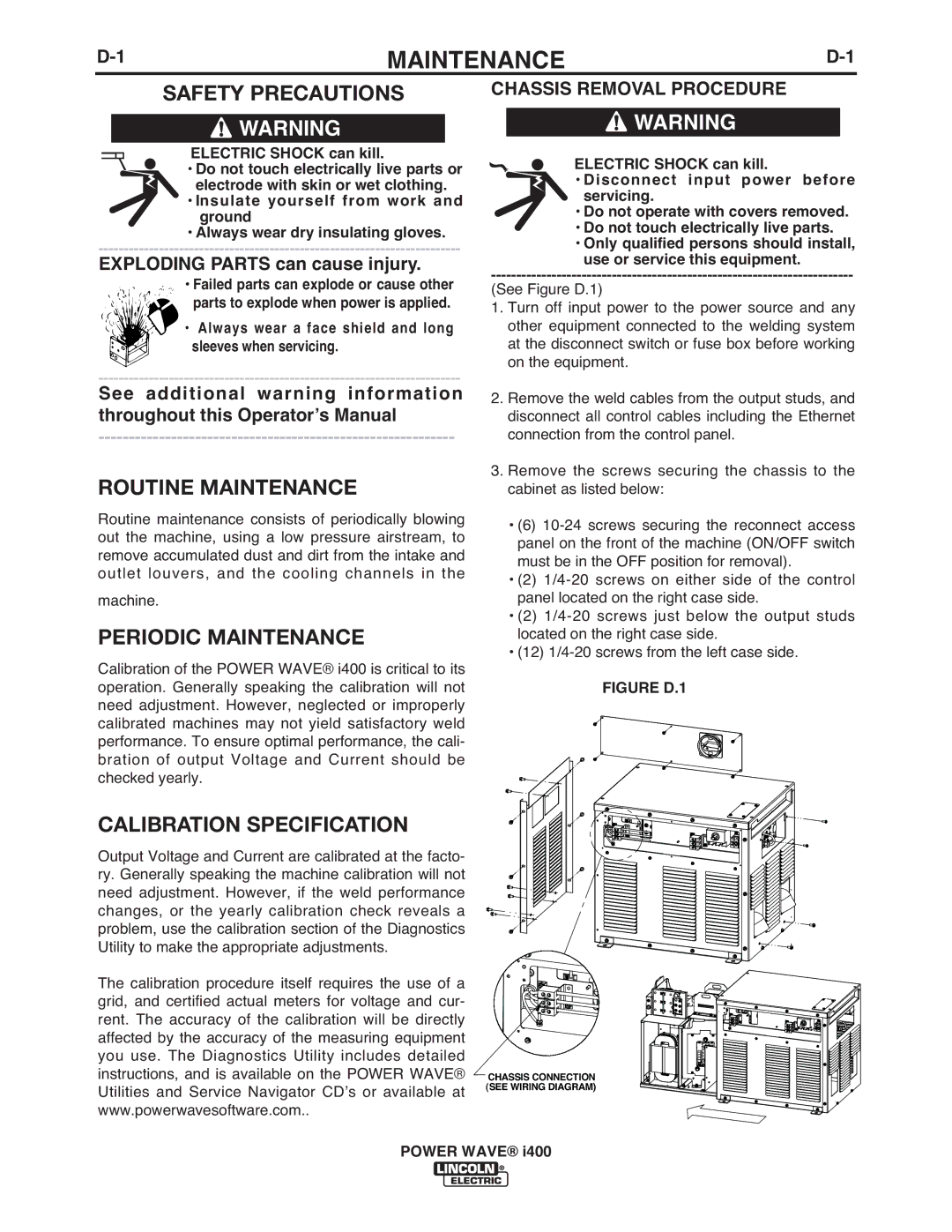
(See Figure D.1)
1.Turn off input power to the power source and any other equipment connected to the welding system at the disconnect switch or fuse box before working on the equipment.
2.Remove the weld cables from the output studs, and disconnect all control cables including the Ethernet connection from the control panel.
3.Remove the screws securing the chassis to the cabinet as listed below:
•(6)
•(2)
•(2)
•(12)
FIGURE D.1
CHASSIS CONNECTION (SEE WIRING DIAGRAM)
POWER WAVE® i400