OPERATION | ||
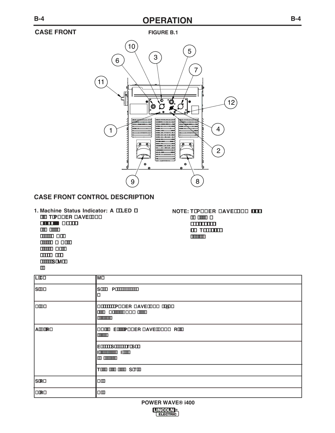
CASE FRONT | FIGURE B.1 |
|
10 | 3 | 5 | |
6 | |||
| |||
| 7 | ||
|
| ||
11 |
|
| |
|
| 12 | |
1 |
| 4 | |
|
| 2 | |
9 |
| 8 |
CASE FRONT CONTROL DESCRIPTION
1.Machine Status Indicator: A two color LED that indicates system errors. The POWER WAVE® i400 is equipped with two indicators. One is for the inverter power source, while the other indicates the status of the feeder control system. Normal opera- tion is a steady green light. . Basic error conditions are indicated in the table below. For more informa- tion and a detailed listing, see the troubleshooting section of this document or the Service Manual for this machine.
NOTE: The POWER WAVE® i400 status light will flash green, and sometimes red and green, for up to one minute when the machine is first turned on. This is a normal situation as the machine goes through a self test at power up
Light Condition | Meaning |
Steady Green | System is okay. Power source communicating normally with the wire feeder and its compo- |
| nents. |
|
|
Blinking Green | Occurs during a reset and indicates the POWER WAVE® i400 is mapping (identifying) each |
| component in the system. Normally this occurs for the first |
| on or if the system configuration is changed during operation. |
|
|
Alternating Green and Red | |
| code before the machine is turned off. |
|
|
| Error code interpretation through the Status light is detailed in the Trouble Shooting section. |
| Individual code digits are flashed in red with a long pause between digits. If more than one code |
| is present, the codes will be separated by a green light. |
|
|
| To clear the error, turn power source off, and back on to reset. See Troubleshooting section. |
|
|
Steady Red | Not applicable |
|
|
Blinking Red | Not applicable |
|
|
POWER WAVE® i400