INSTALLATION |
Work Voltage Sensing
The POWER WAVE® i400 is configured at the factory to sense work voltage at the negative output stud (positive output polarity with remote Work Voltage Sensing disabled).
![]() CAUTION
CAUTION
Negative electrode polarity operation WITHOUT use of a remote work sense lead (21) requires the Negative Electrode Polarity attribute to be set via the Fanuc Teach Pendant or with the Weld Manager Utility (included on the Power Wave Utilities and Service Navigator CDʼs or available at www.powerwavesoftware.com).
While most applications perform adequately by sens- ing the work voltage directly at the output stud, the use of a remote work voltage sense lead is recom- mended for optimal performance. The remote WORK sense lead (21) can be accessed through the
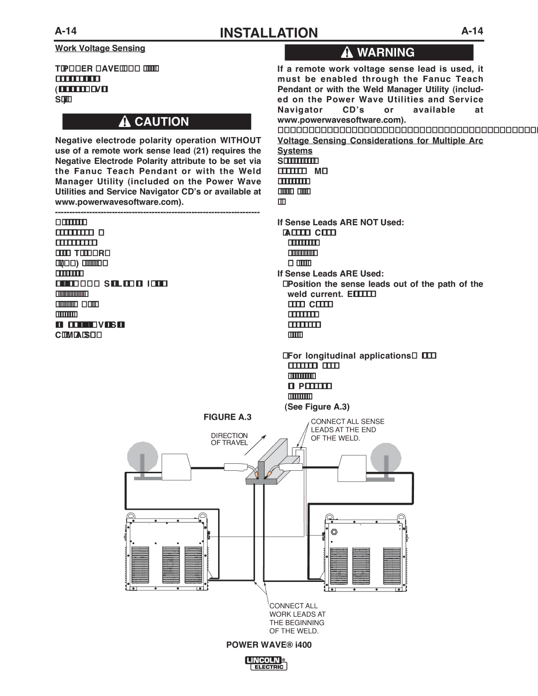
FIGURE A.3
DIRECTION
OF TRAVEL
![]() WARNING
WARNING
If a remote work voltage sense lead is used, it must be enabled through the Fanuc Teach Pendant or with the Weld Manager Utility (includ- ed on the Power Wave Utilities and Service Navigator CDʼs or available at www.powerwavesoftware.com).
Voltage Sensing Considerations for Multiple Arc Systems
Special care must be taken when more than one arc is welding simultaneously on a single part. Multiple arc applications do not necessarily dictate the use of remote work voltage sense leads, but they are strong- ly recommended.
If Sense Leads ARE NOT Used:
•Avoid common current paths. Current from adja- cent arcs can induce voltage into each others cur- rent paths that can be misinterpreted by the power
sources, and result in arc interference.
If Sense Leads ARE Used:
•Position the sense leads out of the path of the weld current. Especially any current paths com- mon to adjacent arcs. Current from adjacent arcs can induce voltage into each others current paths that can be misinterpreted by the power sources, and result in arc interference.
•For longitudinal applications, connect all work leads at one end of the weldment, and all of the
work voltage sense leads at the opposite end of the weldment. Perform welding in the direction away from the work leads and toward the sense leads.
(See Figure A.3)
CONNECT ALL SENSE
LEADS AT THE END
OF THE WELD.
CONNECT ALL WORK LEADS AT THE BEGINNING OF THE WELD.
POWER WAVE® i400