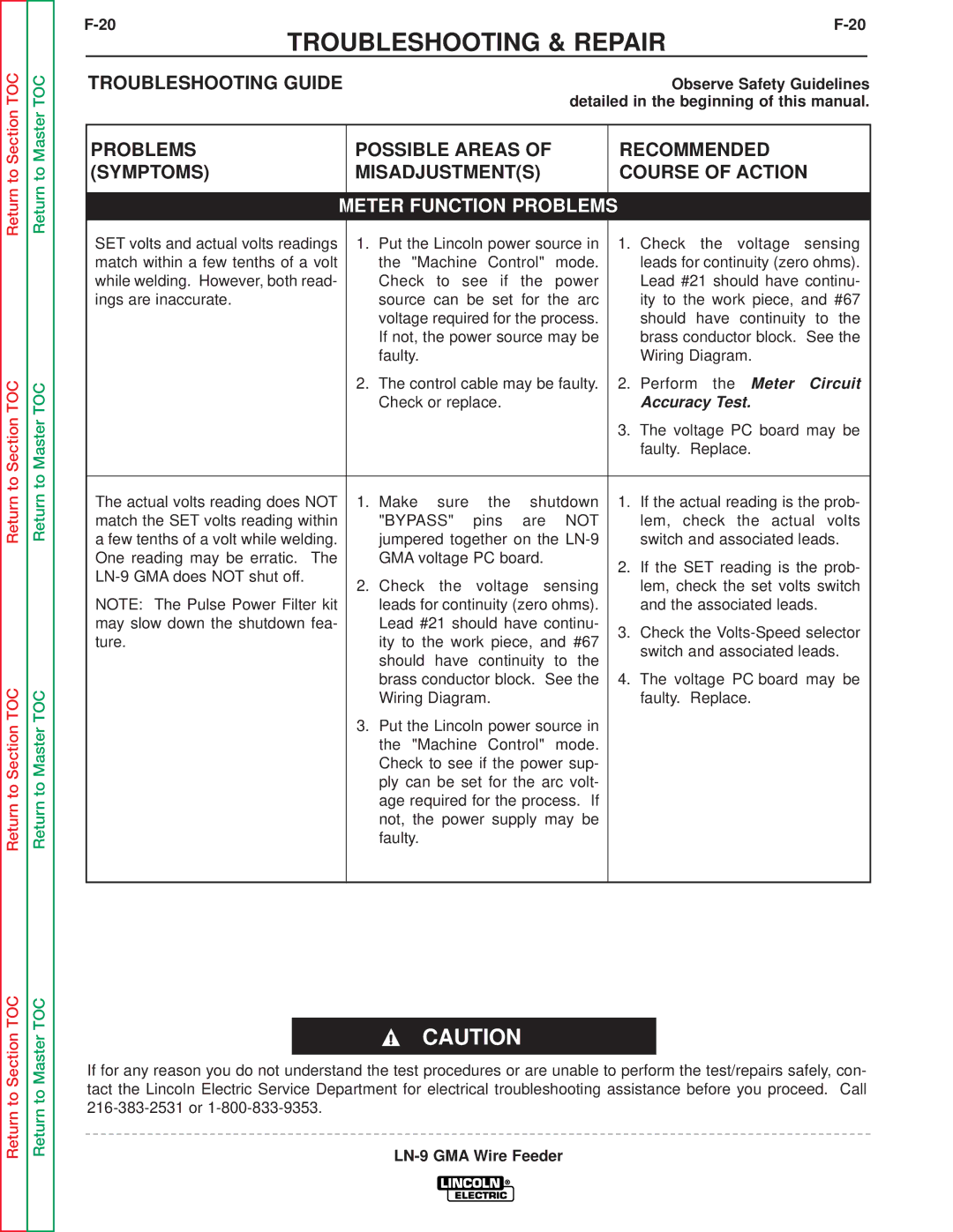
Return to Section TOC
Return to Section TOC
Return to Section TOC
Return to Section TOC
Return to Master TOC
Return to Master TOC
Return to Master TOC
Return to Master TOC
|
|
|
|
|
|
|
|
| |||
TROUBLESHOOTING & REPAIR |
| ||||||||||
TROUBLESHOOTING GUIDE |
|
|
|
|
|
|
| Observe Safety Guidelines | |||
|
|
|
|
|
|
| detailed in the beginning of this manual. | ||||
|
|
|
|
|
| ||||||
PROBLEMS |
| POSSIBLE AREAS OF |
|
| RECOMMENDED | ||||||
(SYMPTOMS) |
| MISADJUSTMENT(S) |
|
| COURSE OF ACTION | ||||||
|
|
|
|
|
|
| |||||
|
| METER FUNCTION PROBLEMS |
|
|
|
| |||||
SET volts and actual volts readings |
| 1. | Put the Lincoln power source in |
| 1. Check the voltage sensing | ||||||
match within a few tenths of a volt |
|
| the "Machine | Control" | mode. |
|
| leads for continuity (zero ohms). | |||
while welding. However, both read- |
|
| Check to see if the power |
|
| Lead #21 should have continu- | |||||
ings are inaccurate. |
|
| source can be set for the arc |
|
| ity to the work piece, and #67 | |||||
|
|
| voltage required for the process. |
|
| should have continuity to the | |||||
|
|
| If not, the power source may be |
|
| brass conductor block. See the | |||||
|
|
| faulty. |
|
|
|
|
|
| Wiring Diagram. | |
|
| 2. | The control cable may be faulty. |
| 2. Perform the Meter Circuit | ||||||
|
|
| Check or replace. |
|
|
|
| Accuracy Test. | |||
|
|
|
|
|
|
|
|
| 3. The voltage PC board may be | ||
|
|
|
|
|
|
|
|
|
| faulty. Replace. | |
|
|
|
|
|
|
|
|
|
| ||
The actual volts reading does NOT |
| 1. | Make sure |
| the | shutdown |
| 1. | If the actual reading is the prob- | ||
match the SET volts reading within |
|
| "BYPASS" | pins | are | NOT |
|
| lem, check the actual volts | ||
a few tenths of a volt while welding. |
|
| jumpered together on the |
|
| switch and associated leads. | |||||
One reading may be erratic. The |
|
| GMA voltage PC board. |
|
| 2. | If the SET reading is the prob- | ||||
|
|
|
|
|
|
|
| ||||
| 2. Check the | voltage sensing |
|
| lem, check the set volts switch | ||||||
|
|
|
| ||||||||
NOTE: The Pulse Power Filter kit |
|
| leads for continuity (zero ohms). |
|
| and the associated leads. | |||||
may slow down the shutdown fea- |
|
| Lead #21 should have continu- |
| 3. Check the | ||||||
ture. |
|
| ity to the work piece, and #67 |
| |||||||
|
|
|
| switch and associated leads. | |||||||
|
|
| should have continuity to the |
|
| ||||||
|
|
|
|
|
|
| |||||
|
|
| brass conductor block. See the |
| 4. | The voltage PC board may be | |||||
|
|
| Wiring Diagram. |
|
|
|
| faulty. Replace. | |||
|
| 3. Put the Lincoln power source in |
|
|
|
| |||||
|
|
| the "Machine | Control" | mode. |
|
|
|
| ||
|
|
| Check to see if the power sup- |
|
|
|
| ||||
|
|
| ply can be set for the arc volt- |
|
|
|
| ||||
|
|
| age required for the process. If |
|
|
|
| ||||
|
|
| not, the power supply may be |
|
|
|
| ||||
|
|
| faulty. |
|
|
|
|
|
|
|
|
|
|
|
|
|
|
|
|
|
|
|
|
CAUTION
If for any reason you do not understand the test procedures or are unable to perform the test/repairs safely, con- tact the Lincoln Electric Service Department for electrical troubleshooting assistance before you proceed. Call
