Safety Depends on You
LN-9 GMA Wire Feeder
LN-9 GMA Wire Feeder
Safety
Electric Shock can kill
ARC Rays can burn
Fumes and Gases can be dangerous
Iii
Cylinder may explode if damaged
Précautions DE Sûreté
Master Table of Contents
Master Table of Contents cont’d
Vii LN-9 GMA Wire Feeder
Section A-1
Table of Contents
Installation Section
Installation
Installation
Technical Specifications
Width Height
Mounting the Unit
Installing the LN-9 GMA Roll and 4-ROLL Models
Attaching the Wire Reel Stand
Mounting the Wire Feed Unit
Power Input Cable Assembly
Electrical Connections LN-9 GMA and LN-9F GMA
Routing the Electrode
Bottom View
Connecting the Power Input Cable Assembly to Power Sources
Installation
Can kill
Figure A.5 Connection of LN-9 GMA to DC-600 Power Sources
Figure A.6 Connection of LN-9 GMA to DC-1000 Power Sources
To LN-9 GMA Input Cable Plug
Figure A.8 Connection of LN-9 GMA to V300 Power Sources
Table A.1 Work Cable Sizes
Machine Grounding
Work Cable Connection
Direct Work Lead Connection
Connecting the GUN Cable to the Wire Feeder
For GMA GUN Cables
Thumb- screw
Cylinder may explode if damaged
Hooking UP GMA Shielding GAS
Table of Contents Operation Section
Safety Precautions
Operation
Operating Instructions
K436 LN-9F GMA 2-ROLL and K583-1 LN-9F GMA 4-ROLL
General Description
Recommended Processes and Equipment
K424 LN-9 GMA 2-ROLL and K568-1 LN-9 GMA 4-ROLL
DC Constant Voltage Power Sources
Controls and Settings
Figure B.3 Wire Feeder Controls for LN-9 GMA
Figure B.4 Wire Feeder Controls for LN-9F GMA
Circuit Breaker
Power Supply Fuse
Circuit Protection and Automatic Shutdown
Avoiding Grounding Lead Protector GLP Shutdown
Automatic Shutdown
Changing Drive Rolls for 2-ROLL Wire Feeders
Drive Roll Installation
Guide Tube Detail
Changing Drive Rolls for 4-ROLL Wire Feeders
Large
Figure B.7a Threaded Locking Collar
Wire Loading
Feeding Electrode and Brake Adjustment
Loading a 50-60 LB .7-27.2 KG. Coil Using K1504-1 Coil Reel
Loading a 50 or 60 LB. Coil
Adjustable Wire Reel Brake
Feeding Electrode and Brake Adjustment
Roll Wire Feeders
Idle Roll Pressure Setting
DC-250, DC-400, or DC-600
Adjust the Power Source
Adjust the LN-9 GMA Controls
Pulse Power 500, DC650 PRO
Select Acceleration
Starting Characteristics
RUN-IN Feature
Voltage Control Response
Procedure AT END of Coil
Security of Weld Procedure Settings
Making a Weld
LN-9 GMA Wire Feeder
Table of Contents Accessories Section
Wire Reel Stands and Mountings
Accessories
Optional Equipment and Accessories
Power Input Cable Assemblies K196, K595, K596
Spindle for READI-REELS and 2 I.D. Spools K162-H
Attaching the Wire Reel Stands
Wire Reel Door KIT
50-60 LB. Wire Reel Assembly for Customer Mounting K299
Universal Wire Reel Stand K1524-1
Table C.1 LN-9 GMA GUN and Cable Assemblies
Wire Feeder Accessories
Burnback Timer KIT K419
GUN and Cable Assemblies
Pulse Power Filter Conversion KIT K442-1
GMA Timer KIT K418
Dual Process KIT K317 For Wire Feeders
Dual Procedure KIT K319
K320 Flux Tank Loading
Swivel Platform K178-1
Undercarriage K163
Continuous Flux Feed Tank K320
K58 Magnetic Separator
Aluminum Electrode
Table C.2 Drive Roll and Guide Tube Kits
Kit Roll Solid Steel Electrode
Cored Electrode
LN-9 GMA Wire Feeder
Table of Contents Maintenance Section
Maintenance
Routine Maintenance
Periodic Maintenance
GUN and Cable Maintenance
Proper Speed Sensor Module Mounting
3D-3
Figure D.2 LN-9 GMA Connectors
Table of Contents Theory of Operation Section
Theory of Operation
Figure E.2 Power Input Circuits
Figure E.3 Trigger and Shutdown Circuit
Trigger and Shutdown Circuit
Figure E.4 ARC VOLTAGE, Wire Speed Control and Metering
ARC VOLTAGE, Wire Speed Control and Metering
Power Board
Printed Circuit Board Functions
Control Board
LN-9 GMA Wire Feeder
Table of Contents Troubleshooting & Repair Section
HOW to USE Troubleshooting Guide
Troubleshooting & Repair
PC Board can be damaged by static electricity
PC Board Troubleshooting Procedures
Troubleshooting Guide
Observe Safety Guidelines
Detailed in the beginning of this manual
Trigger
Troubleshooting & Repair
Troubleshooting & Repair
Troubleshooting Guide
Troubleshooting & Repair
Interlock Function Problems
Test
T2 Transformer
Troubleshooting & Repair
Range Shutdown Test
Feeding Problems
Welding Problems
Troubleshooting & Repair
Meter Function Problems
Hall Effect
Bypass
Starting Problems
Troubleshooting & Repair
Starting Problems
T1 Transformer Test
Description
Materials Needed
T1 Transformer Test
Test Procedure
Figure F.2 Secondary Leads #601 and #602 AT Lead Splices
T2 Transformer Test
T2 Transformer Test
Figure F.3 Protection Circuit Troubleshooting Nameplate
Circuit Breaker Lead 32A
Lead Lead
Wire Drive Motor Test
Wire Drive Motor Test
Electric Shock can kill
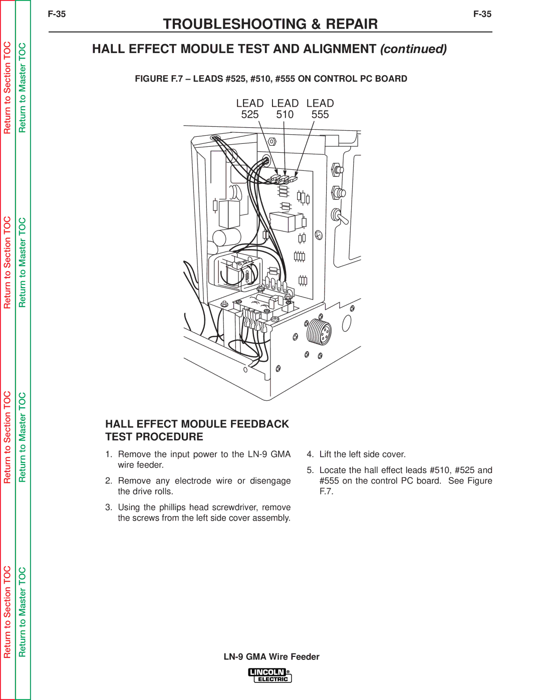
Hall Effect Module Test and Alignment
Hall Effect Module Test and Alignment
Hall Effect Module Feedback Test Procedure
Test
Figure F.8 Hall Effect Module Location
Hall Effect Module Alignment Test Procedure
Voltmeter Accuracy Test
Figure F.9 Voltmeter Connection Point
Voltmeter Accuracy Test
Return Return to Master TOC
Meter Circuit Accuracy Test
Figure F.10 Meter PC Board Locations and Cover
Meter Circuit Accuracy Test
Figure F.11 Meter PC Board Test Points
Test Meter PC Board Voltage Accuracy
Test Meter PC Board Wire Feed Speed
Metric Model Metric Range SET M/MIN Reading Test Voltmeter
Test Meter PC Board Wire Feed Speed Accuracy
Wire Speed Accuracy Test
Check for the proper drive roll revolutions per minute
Wire Speed Accuracy Test
OUT of Voltage Range Shut Down Test
Figure F.12 Voltage PC Board with Jumpers
OUT of Voltage Range Shut Down Test
Section TOC
General Power Supply Tests
Also perform the T1 Transformer Test
General Power Supply Tests
General Power Supply Checks
Digital Meter and Meter PC Board Removal Replacement
Meter PC Board Removal
Replacement
Procedure
Digital Meter and Meter PC Board Removal
Replacement Procedure
Digital Meter Removal Procedure
Reed Switch CR2 Removal and Replacement
Replacement
Reed Switch CR2 Removal and Replacement
T1 Transformer Removal and Replacement
Figure F.17 Primary Lead #31 AT R1 Resistor
T1 Transformer Removal and Replacement
Figure F.18 Leads #526 and #527 AT Power PC Board
NUT and Screw Control PC Board 1CR Relay Phillips Screws
T1 Transformer Mounting Screws Terminal Strip
Drive Motor Removal and Replacement
Figure F.22 TOP Motor Plate Screws
Drive Motor Removal and Replacement
Nuts and Washers 4-ROLL Feeders
Mylar Insulator Glastic Mounting Board Bolts
Figure F.25 Drive Motor Removal from Gear BOX
Reassembly
Retest After Repair
Retest the LN-9 GMA wire feeder
LN-9 GMA Wire Feeder
Section G
LN-9 GMA Wire Feeder
Electrical Diagrams
Wiring Diagram-LN-9 GMA
LN-9 GMA
DEC
Wiring Diagram-LN-9F GMA
LN9, LN9F, LN9GMA, LN9FGMA
Voltage Board Schematic
SHT. no
Power PC Board Schematic
17950 M
Trigger PC Board Schematic
Circuit
PM Control Schematic
21146
Meter Board Schematic
525 B
Operating Schematic