Section 2: Installation
Preparation
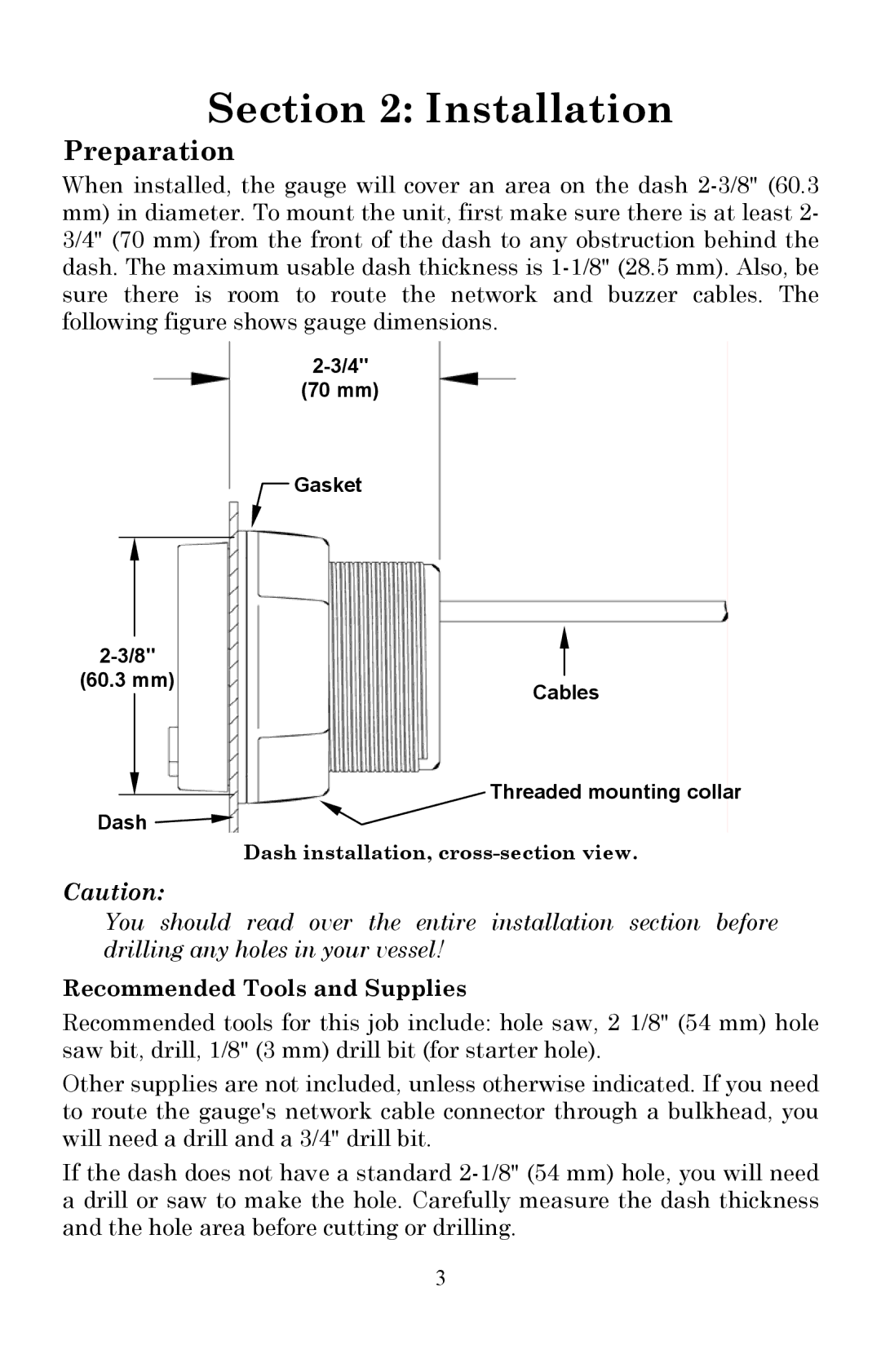
When installed, the gauge will cover an area on the dash
mm)in diameter. To mount the unit, first make sure there is at least 2- 3/4" (70 mm) from the front of the dash to any obstruction behind the dash. The maximum usable dash thickness is
(70 mm)
![]() Gasket
Gasket
| |
(60.3 mm) | Cables |
|
Threaded mounting collar
Dash ![]()
Dash installation,
Caution:
You should read over the entire installation section before drilling any holes in your vessel!
Recommended Tools and Supplies
Recommended tools for this job include: hole saw, 2 1/8" (54 mm) hole saw bit, drill, 1/8" (3 mm) drill bit (for starter hole).
Other supplies are not included, unless otherwise indicated. If you need to route the gauge's network cable connector through a bulkhead, you will need a drill and a 3/4" drill bit.
If the dash does not have a standard
3