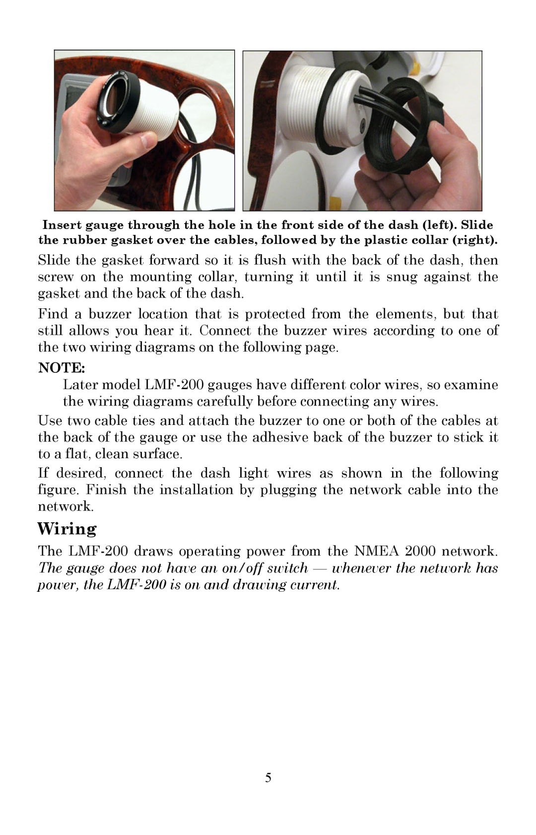
Insert gauge through the hole in the front side of the dash (left). Slide the rubber gasket over the cables, followed by the plastic collar (right).
Slide the gasket forward so it is flush with the back of the dash, then screw on the mounting collar, turning it until it is snug against the gasket and the back of the dash.
Find a buzzer location that is protected from the elements, but that still allows you hear it. Connect the buzzer wires according to one of the two wiring diagrams on the following page.
NOTE:
Later model
Use two cable ties and attach the buzzer to one or both of the cables at the back of the gauge or use the adhesive back of the buzzer to stick it to a flat, clean surface.
If desired, connect the dash light wires as shown in the following figure. Finish the installation by plugging the network cable into the network.
Wiring
The
5