Disassembly Procedures
!WARNING
To avoid risk of electrical shock, personal injury, or death: disconnect electrical and gas supply before servicing.
Removing and Replacing Range
1.Turn off power to the range at the circuit breaker.
2.Turn off gas supply line to unit.
3.Pull the range forward out of the cabinet opening.
4.Unplug the power cord leading from unit to outlet.
5.Replace the range using the installation instructions and
Maintop Assembly
1.Turn power off to unit.
2.Remove sealed burners, see "Sealed Burner" procedure.
3.Remove screws securing main top to orifice holder assembly.
4.Raise the front edge of the maintop and pull forward.
5.Lift maintop assembly from the oven chassis.
6.Reverse procedure to reinstall maintop assembly.
4.Reverse procedure to reinstall control board assembly.
Rocker Switch
1.Remove control panel, see "Control Panel" procedure steps 1 through 7.
2.Disconnect and label wire terminals from rocker switch.
3.Squeeze tabs on rocker switch and push outward to release from control panel.
4 . Reverse procedure to reinstall indicator light.
Top Surface Valve and Spark Switch
1.Remove front control panel, see "Front Control Panel" procedure, steps 1 through 4.
2.Remove spark switch by pulling straight off valve.
3.Remove screw securing valve to front manifold.
4.Replace and reassemble in reverse order.
Front Control Panel
1.Open or remove oven door from unit.
2.Remove control knobs from gas valves, by pulling.
3.Remove screws located on the bottom edge of the front control panel.
4.Remove control panel by sliding one way or the other and pulling away from the unit.
5.Reverse procedure to reassemble.
Control Panel
1.Remove maintop assembly, see "Maintop Assembly" procedure, steps 1 through 4.
2.Remove screws securing control panel heat shield.
3.Remove screws securing bottom outside edges of the control panel.
4.Pull unit out from the wall far enough to allow the back outside screws to be loosened.
5.Loosen the back outside screws securing control panel to backguard.
6.Grasp front lower outside edges of the control panel and push inward on the outside edges of the backguard to release the control panel front.
NOTE: Front edges of the control panel are difficult to release from backguard.
7.Once the control panel bottom edges are free, pull control panel forward and raise the control panel upward to release screws securing top back edges and allow control panel to tip forward.
8.Reverse procedure to reinstall control panel.
Control Board Assembly
1.Remove control panel, see “Control Panel” procedure, steps 1 through 7.
2.Remove screws securing control board bracket to control panel.
3.Label and disconnect terminal plug from control board assembly.
Sealed Burner
1.Turn off electrical power and gas to the range.
2.Disconnect gas and power from unit.
3.Remove grates.
4.Obtain Burner Wrench (removal and installation tool, P/N
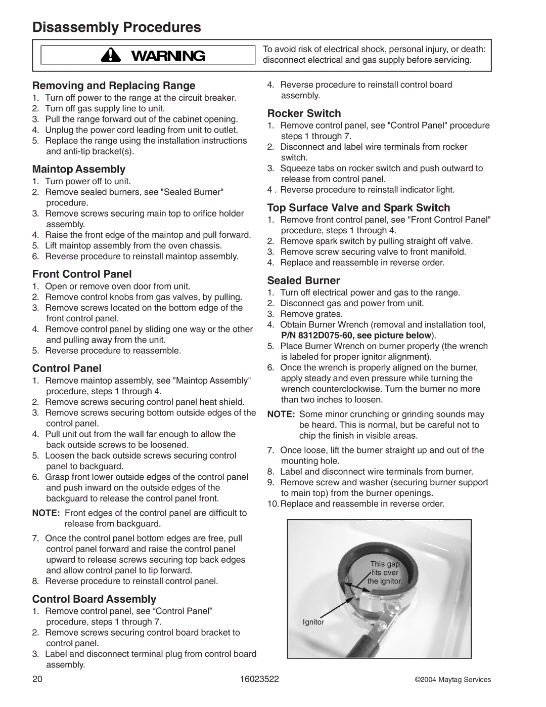
5.Place Burner Wrench on burner properly (the wrench is labeled for proper ignitor alignment).
6.Once the wrench is properly aligned on the burner, apply steady and even pressure while turning the wrench counterclockwise. Turn the burner no more than two inches to loosen.
NOTE: Some minor crunching or grinding sounds may be heard. This is normal, but be careful not to chip the finish in visible areas.
7.Once loose, lift the burner straight up and out of the mounting hole.
8.Label and disconnect wire terminals from burner.
9.Remove screw and washer (securing burner support to main top) from the burner openings.
10.Replace and reassemble in reverse order.
This gap fits over the ignitor.
Ignitor
20 | 16023522 | ©2004 Maytag Services |