Parts Catalog OCB429
Contents
Indoor Unit
Reference Manual
Always Observe for Safety
Safety Precaution
Additional refrigerant charge
When charging directly from cylinder
R22
PUZ-A42NHA2 PUZ-A42NHA2-BS PUY-A42NHA2 PUY-A42NHA2-BS
Features
PUZ-A18NHA2 PUZ-A18NHA2-BS PUY-A12/18NHA2 PUY-A12/18NHA2-BS
PUZ-A18NHA2 PUZ-A24NHA2 PUZ-A30NHA2 PUZ-A36NHA2 PUZ-A42NHA2
Specifications
PUY-A18NHA2-BS PUY-A24NHA2-BS
Data
Compressor Technical Data
PUZ-A18NHA2-BS
Noise Criterion Curves
Heat pump
Standard Operation Data
PKA-A12GA PKA-A18GA PKA-A24FA PKA-A30FA PKA-A36FA PLA-A42BA
Cooling only
Unit mminch
Outdoor Unit
Example of Notes
662-5/8 Air outlet
Service Space
NET Adapter
Wiring Diagram
NET Adapter
PUZ-A24NHA2 PUZ-A24NHA2-BS PUY-A24NHA2 PUY-A24NHA2-BS
WUse copper supply wires
TABU/V/W
System Simultaneous twin system
Wiring Specifications
OFF
Separate Indoor UNIT/OUTDOOR Unit Power Supplies
Indoor Outdoor Connecting Cable
Refrigerant address NET address Control Remote Controller
NET Wiring Method
NET wiring
NET address setting
Refrigerant address setting
Regulations in address settings
Way valve solenoid coil Heating on Cooling OFF
Refrigerant System Diagram
PUZ-A18NHA2 PUZ-A18NHA2-BS
PUZ-A42NHA2 PUZ-A42NHA2-BS
PUY-A42NHA2 PUY-A42NHA2-BS
PUY-A12/18NHA2 PUY-A12/18NHA2-BS
Start and finish of test run
Refrigerant recovering pump down
Before test run
Troubleshooting
Troubleshooting
Check Point Under Test RUN
Contents of inferior phenomena
Operating procedures
Symptoms in test run mode Cause Remote Controller Display
Test run for wireless remote controller
Self-Diagnosis During Maintenance or Service
HOW to Proceed SELF-DIAGNOSIS
When a Problem Occurs During Operation
ON/OFF
Remote Controller Diagnosis
Case of trouble during operation
Malfunction-diagnosis method by wireless remote controller
Malfunction-diagnosis method at maintenance service
Procedure
U9,UH
Cndc
Error Code Abnormal point and detection method Case
63L connector open
SELF-DIAGNOSIS Action Table
Indoor/outdoor unit connector
Error Code
Case Judgment and action 63H connector open
Connector open
63H worked
Case Judgment and action High pressure High-pressure switch
High discharging temperature
Abnormalities detected while unit is operating
Case Judgment and action Open/short circuit of discharge
Temperature thermistor TH4
Temperature of heatsink
Power module
Case Judgment and action Outdoor fan motor
Synchronous signal to main circuit
When compressor locked
Current sensor error
Case Judgment and action Low pressure 63L worked
Remote controller transmission
ErrorE0/signal receiving errorE4
Remote controller control board
Non defined error code
Case Judgment and action Remote controller transmission
ErrorE3/signal receiving errorE5
Error Signal receiving error
Case Judgment and action Address duplicate definition
NET communication error
Case Judgment and action Pipe temperature
Hardware error of transmission
To the next
Lossnay
From the previous
Fresh Master
Master
Phenomena Factor Countermeasure
Troubleshooting by Inferior Phenomena
VCTF, VCTFK, CVV CVS, VVR, VVF, VCT
Melans
YES
Please Wait
Miswiring, breaking
Outdoor power circuit board
Power supply To the outdoor unit Check the breaker
Outdoor connecting wire
Breaking or poor Fix the breaking or poor
Indoor/outdoor connecting wire Blinking
Defective indoor Replace the indoor Power board
Not lighting
Check if there is breaking
Action Table
Before repair Frequent calling from customers
This is not a malfunction
Phone Calls From Customers How to Respond
Sometimes This is the sound which is heard when the flow
Refrigerant in the air conditioner is switched
There might be a case that
With Blower…
With Airflow Direction…
Page
HOW to Check the Parts
END
Wiring contact check
Power supply check Remove the connector CNF1
Fuse check
High temperature thermistor
HOW to Check the Components
Thermistor feature chart Low temperature thermistors
Medium temperature thermistor
Linear expansion valve operation
Output pulse signal and the valve operation
Operation summary of the linear expansion valve
Linear expansion valve A24, 30, 36
How to attach the coil
How to detach the coil
Be sure to attach the stopper
SW4
Emergency operation procedure
Emergency Operation
Releasing emergency operation
Operation data during emergency operation
Test Point Diagram
LO, no
LI, NI
CNAC1, CNAC2
CN5
PUZ-A24NHA2 PUZ-A24NHA2-BS PUY-A24NHA2 PUY-A24NHA2-BS
RS1
CN3 CN4 CN5
LD1-LD2
DIP-PFC
DIP-IPM
Actm
Cnaf
CN3
TABP2/SC-P2
L1, L2
Upper side
Lower side
OFF
Function of SWITCHES, Connectors and Jumpers
Function of switches
Function Action by the switch operation Effective timing
SW9
2Function of connector
75%
Special function
50%
Display function of inspection for outdoor unit
1Check the outdoor fan motor 1Check if stop valves are open
Blinking Abnormality of outdoor fan Motor rotational speed
Digital indicator LED1 working details
Operation indicator
Lighting Cancellation of postponement
Example When 42500 times 425 100 times Secs 5secs
~9999 When it is 100 hours or more, hundreds digit, tens
Example When 2450 hours 245 10 hours
SW2 setting Display detail Explanation for display Unit
Cooling only
Outdoor unit setting information
Single phase 2 3 phase
Unit
DegF
Fan step on error occurring ~10 Step
Example When 130 pulse
U9 Error status during the Error
Discharge superheat on error occurring ~327 0~182degC SHd
Secs Sub cool on error occurring. SC ~234 0~130degC
Example When 415 minutes Minute Secs
LED
Rise of discharge temperature
Fixed Hz operation
Easy Maintenance Function
Maintenance Mode Operation Method
Switching to maintenance mode
To check the data for each item, repeat steps 5 to
Data measurement
Guide for Operation Condition
Average data Initial Ta=A+B/2 Sensor on all
Function Setting
Unit Function Setting by the Remote Controller
Data of the sensor Ta=C On main remote Controller
PLA-BA PCA-GA
Mode No.11
Setting No Settings
Press E FAN operation
Selecting functions using the wired remote controller
For modes 15 and higher
Specified indoor unit
Operating Procedure
Operating instructions
Flow of function selection procedure
Mode Selection
Function Selection of Remote Controller
Function selection flowchart
FAN
Mode Vane
Press
Button for 3 seconds to switch to Maintenance monitor
Check button for 3 seconds to return to maintenance mode
Turn on the Monitoring the operation data
Request Code List
Outdoor unit-Control state
Code Description
For indoor fan pulsation control
100
101
Detail Contents in Request Code
Actuator output state Request code
Error content U9 Request code
102
Fan control state Request code
Contact demand capacity Request code
Outdoor unit --Capacity setting display Request code
Outdoor unit Setting information Request code
103
104
Data display See the table on the right
Indoor unit Model setting information Request code
Indoor unit Capacity setting information Request code
105
Photo
Disassembly Procedure
PUZ-A18NHA2 PUZ-A18NHA2-BS Operating Procedure Photos
106
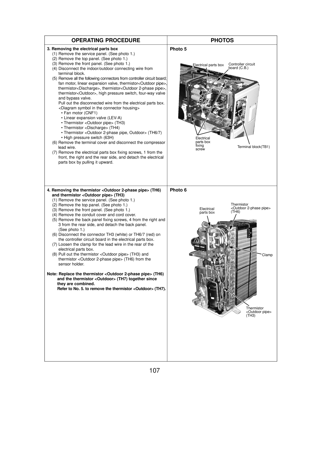
Thermistor Outdoor pipe TH3
Removing the thermistor Outdoor 2-phase pipe TH6
107
Removing the electrical parts box
108
Operating Procedure Photos
Removing linear expansion valve
109
Removing the 4-way valve
Removing the accumulator
Separator Recover refrigerant
110
Removing the compressor MC
Removing the fan motor MF1
Operating Procedure Photos & Illustration
Removing the service panel and top panel
111
Thermistor Discharge TH4
112
Removing the thermistor Outdoor pipe TH3
Removing the bypass valve coil
113
Removing the 4-way valve coil
Removing the linear expansion valve coil
Removing the reactor ACLA24
114
Removing the bypass valve
Remove 2 receiver leg fixing screws 4
115
Removing the reactor DCL A30
Removing the fan motor MF1, MF2
116
Remove the top panel. See figure Controller
Remove the service panel. See figure Outdoor pipe
117
Coil Valve coil
118
Are not oxidized
Linear expansion
DCL
Low pressure switch 63L
119
Removing the reactor DCL and capacitor CE
Remove 2 back cover panel fixing screws 5 10