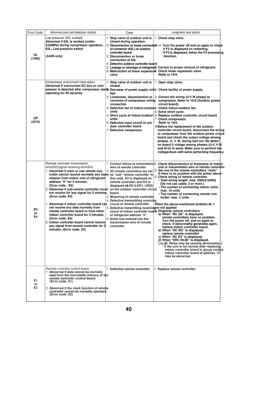
Mitsubishi Electronics PUZ-A18NHA2, PUZ-A30NHA2 Case Judgment and action Low pressure 63L worked

Models: PUZ-A36NHA2-BS PUY-A12NHA2 PUY-A42NHA2-BS PUY-A30NHA2 PUZ-A36NHA2 PUY-A36NHA2-BS PUZ-A18NHA2 PUZ-A18NHA2-BS PUY-A30NHA2-BS PUZ-A30NHA2-BS PUY-A18NHA2 PUY-A36NHA2 PUZ-A30NHA2 PUY-A12NHA2-BS PUZ-A24NHA2-BS PUZ-A42NHA2 PUY-A18NHA2-BS PUY-A42NHA2 PUZ-A42NHA2-BS PUY-A24NHA2-BS PUZ-A24NHA2 PUY-A24NHA2

1 120
Download 120 pages 22.49 Kb
Page 40
Image 40

Error Code

Abnormal point and detection method

Case

Judgment and action


Low pressure (63L worked)

1 Stop valve of outdoor unit is

1 Check stop valve.


Abnormal if 63L is worked (under-

closed during operation.


0.03MPa) during compressor operation.

2 Disconnection or loose connection 2~4 Turn the power off and on again to check


63L: Low-pressure switch

of connector (63L) on outdoor

if F3 is displayed on restarting.

UL


controller board

If F3 is displayed, follow the F3 processing

(A42N only)

3 Disconnection or loose

direction.

(1300)


connection of 63L


4 Defective outdoor controller board


5 Leakage or shortage of refrigerant

5 Correct to proper amount of refrigerant.


6 Malfunction of linear expansion

6 Check linear expansion valve.


valve

Refer to 10-6.


Compressor overcurrent interruption

1 Stop valve of outdoor unit is

1 Open stop valve.


Abnormal if overcurrent DC bus or com-

closed.


pressor is detected after compressor starts

2 Decrease of power supply volt-

2 Check facility of power supply.


operating for 30 seconds.

age


3 Looseness, disconnection or

3 Correct the wiring (U·V·W phase) to


converse of compressor wiring

compressor. Refer to 10-9 (Outdoor power


connection

circuit board).


4 Defective fan of indoor/outdoor

4 Check indoor/outdoor fan.


units

5 Solve short cycle.

UP


5 Short cycle of indoor/outdoor

6 Replace outdoor controller circuit board.


units

7 Check compressor.

(4210)


6 Defective input circuit of out-

Refer to 10-6.


door controller board

W Before the replacement of the outdoor


7 Defective compressor

controller circuit board, disconnect the wiring


to compressor from the outdoor power circuit


board and check the output voltage among


phases, U, V, W, during test run. No defect


on board if voltage among phases (U-V, V-W


and W-U) is same. Make sure to perform the


voltage check with same performing frequency.


Remote controller transmission

1 Contact failure at transmission 1 Check disconnection or looseness of indoor


error(E0)/signal receiving error(E4)

wire of remote controller

unit or transmission wire of remote controller.


1 Abnormal if main or sub remote con-

2 All remote controllers are set

2 Set one of the remote controllers “main”.


troller cannot receive normally any trans-

as “sub” remote controller. In

If there is no problem with the action above.


3 Check wiring of remote controller.


mission from indoor unit of refrigerant

this case, E0 is displayed on


• Total wiring length: max. 500m[1640ft]


address “0” for 3 minutes.

remote controller, and E4 is


(Do not use cable o 3 or more.)


(Error code : E0)

displayed at LED (LED1, LED2)


• The number of connecting indoor units:


2 Abnormal if sub-remote controller could

on the outdoor controller circuit


max. 16 units


not receive for any signal for 2 minutes.

board.


• The number of connecting remote con-


(Error code: E0)

3 Miswiring of remote controller


troller: max. 2 units


1 Abnormal if indoor controller board can

4 Defective transmitting receiving


circuit of remote controller

When the above-mentioned problem of 1~3

E0

not receive any data normally from

5 Defective transmitting receiving

are not applied

remote controller board or from other

circuit of indoor controller board

4 Diagnose remote controllers.

or

indoor controller board for 3 minutes.

of refrigerant address “0”.

a) When “RC OK” is displayed,

E4

(Error code: E4)

6 Noise has entered into the

remote controllers have no problem.


Turn the power off, and on again to


2 Indoor controller board cannot receive

transmission wire of remote


check. If abnormality generates again,


any signal from remote controller for 2

controller.


replace indoor controller board.


minutes. (Error code: E4)


b) When “RC NG” is displayed,


replace remote controller.


c) When “RC E3” is displayed,


d) When “ERC 00-06” is displayed,


[ c),d)Noise may be causing abnormality. ]


If the unit is not normal after replacing


indoor controller board in group control,


indoor controller board of address “0”


may be abnormal.


Remote controller control board

1 Defective remote controller

1 Replace remote controller.

1Abnormal if data cannot be normally read from the nonvolatile memory of the

E1

remote controller control board.

(Error code: E1)

or


E2

2 Abnormal if the clock function of remote


controller cannot be normally operated.


(Error code: E2)

40

Page 40
Image 40
Mitsubishi Electronics PUZ-A18NHA2 Case Judgment and action Low pressure 63L worked, Remote controller transmission