Part II: Installation
The NetCommand™ Setup: Edit Screens
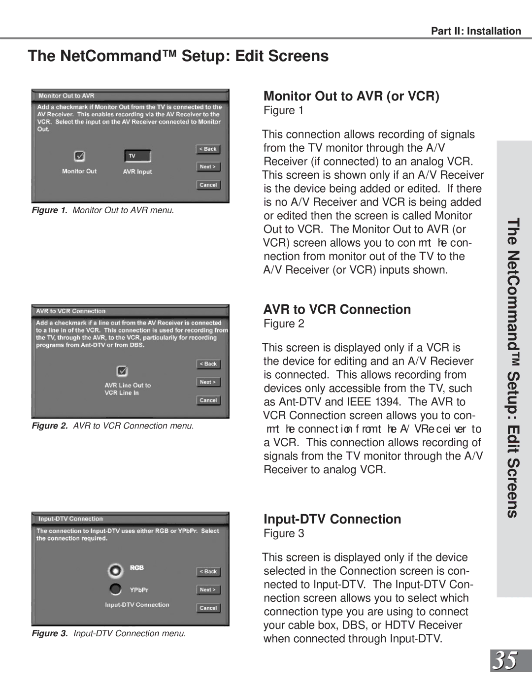
Figure 1. Monitor Out to AVR menu.
Figure 2. AVR to VCR Connection menu.
Figure 3. Input-DTV Connection menu.
Monitor Out to AVR (or VCR)
Figure 1
This connection allows recording of signals from the TV monitor through the A/V Receiver (if connected) to an analog VCR. This screen is shown only if an A/V Receiver is the device being added or edited. If there is no A/V Receiver and VCR is being added or edited then the screen is called Monitor Out to VCR. The Monitor Out to AVR (or VCR) screen allows you to con rmt he con- nection from monitor out of the TV to the A/V Receiver (or VCR) inputs shown.
AVR to VCR Connection
Figure 2
This screen is displayed only if a VCR is the device for editing and an A/V Reciever is connected. This allows recording from devices only accessible from the TV, such as
Input-DTV Connection
Figure 3
This screen is displayed only if the device selected in the Connection screen is con- nected to
The NetCommand™ Setup: Edit Screens
35