Connecting an Analog VCR
TV back panel
Incoming Cable
1
|
| 2 | 3 |
|
VCR back panel |
|
|
|
|
2 |
| AUDIO OUT | AUDIO IN | VIDEO OUT |
IN |
| L | L | (Y/C) |
|
| |||
Antenna | 1 | 2 |
| 1 |
| MONITOR |
![]()
![]() R
R ![]()
![]() R
R
3 ![]()
![]()
![]()
OUT
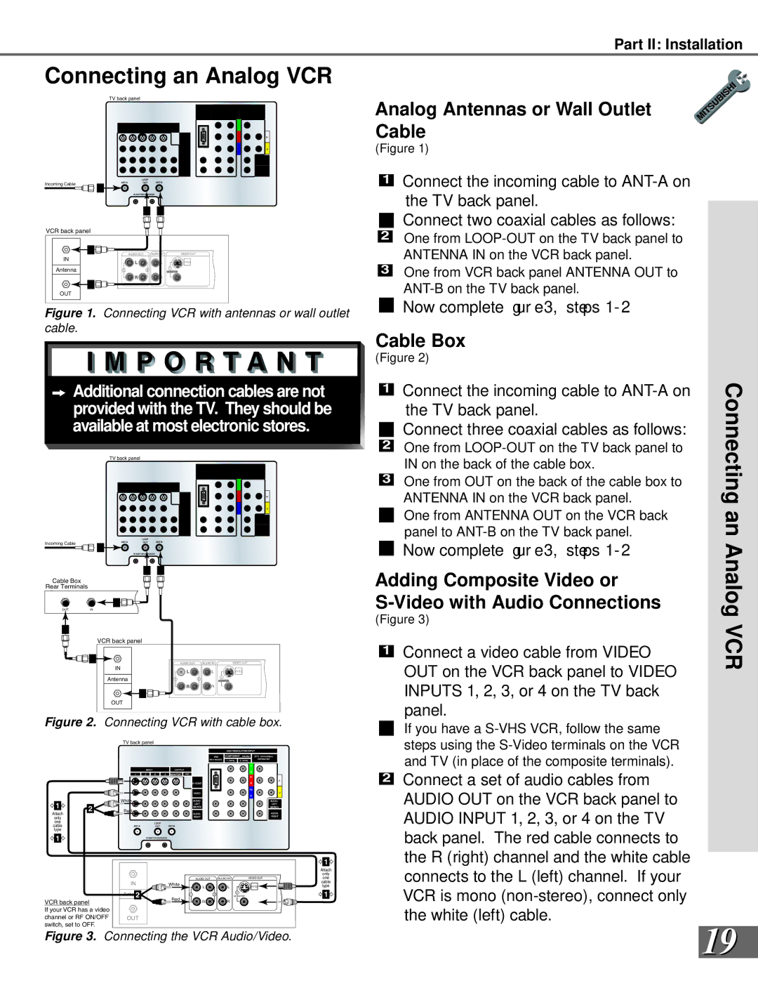
Figure 1. Connecting VCR with antennas or wall outlet cable.
![]()
![]() Additional connection cables are not provided with the TV. They should be available at most electronic stores.
Additional connection cables are not provided with the TV. They should be available at most electronic stores.
TV back panel
Incoming Cable
1
2![]()
![]() 4
4
Cable Box
Rear Terminals
2![]()
![]()
![]()
![]()
OUTIN
3 |
VCR back panel
3 | AUDIO OUT | AUDIO IN | VIDEO OUT |
IN | L | L | (Y/C) |
| |||
Antenna | 1 | 2 | 1 |
MONITOR |
![]()
![]() R
R ![]()
![]() R
R
4 ![]()
![]()
![]()
OUT
Figure 2. Connecting VCR with cable box.
TV back panel
Part II: Installation
Analog Antennas or Wall Outlet Cable
(Figure 1)
1Connect the incoming cable to
the TV back panel.
Connect two coaxial cables as follows:
2One from
3One from VCR back panel ANTENNA OUT to
4Now complete gur e 3, steps 1- 2.
Cable Box
(Figure 2)
| 1 |
| ANTENNA IN on the VCR back panel. | Connecting |
|
| Connect the incoming cable to |
| |
|
|
|
| |
|
|
| the TV back panel. |
|
| 2 |
| Connect three coaxial cables as follows: |
|
|
| One from |
| |
|
|
|
| |
| 3 |
| IN on the back of the cable box. |
|
|
| One from OUT on the back of the cable box to | an | |
|
| |||
|
|
| ||
4 |
| One from ANTENNA OUT on the VCR back | ||
|
|
| panel to | |
5 |
| Now complete gur e 3, steps 1- 2. | Analog | |
|
| |||
Adding Composite Video or |
| |||
|
| |||
(Figure 3) | VCR | |||
| 1 |
| Connect a video cable from VIDEO | |
|
| |||
|
|
|
| |
OUT on the VCR back panel to VIDEO INPUTS 1, 2, 3, or 4 on the TV back panel.
If you have a
1 | 2 | |
Attach | ||
| ||
only |
| |
one |
| |
cable |
| |
type |
|
1
VCR back panel
If your VCR has a video channel or RF ON/OFF switch, set to OFF.
White |
Red |
|
|
|
|
| 1 |
|
|
|
|
| Attach |
|
|
|
|
| only |
|
| AUDIO OUT | AUDIO IN | VIDEO OUT | one |
IN | White |
|
|
| cable |
L | L | (Y/C) | type | ||
2 |
|
|
| 1 | 1 |
Antenna |
| 1 | 2 |
| |
| MONITOR |
| |||
| Red | R | R |
|
|
|
|
|
| ||
OUT |
|
|
|
|
|
2Connect a set of audio cables from AUDIO OUT on the VCR back panel to AUDIO INPUT 1, 2, 3, or 4 on the TV back panel. The red cable connects to the R (right) channel and the white cable connects to the L (left) channel. If your VCR is mono
Figure 3. Connecting the VCR Audio/Video. | 19 |
|