Part II: Installation
Connecting an Analog Antenna, Wall Outlet Cable, or Cable
Box | VHF Antenna | UHF Antenna |
(Channels | (Channels |
Cable Box
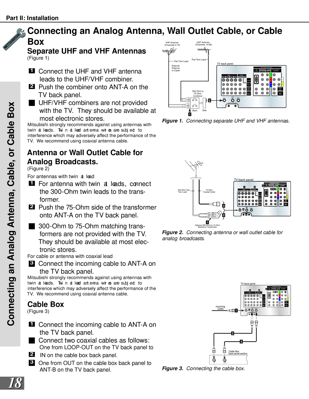
Separate UHF and VHF Antennas
(Figure 1)
1Connect the UHF and VHF antenna leads to the UHF/VHF combiner.
2Push the combiner onto
TV back panel.
![]() UHF/VHF combiners are not provided with the TV. They should be available at most electronic stores.
UHF/VHF combiners are not provided with the TV. They should be available at most electronic stores.
Mitsubishi strongly recommends against using antennas with twin at leads. Twi n at lead ant enna wir es are subj ect to interference which may adversely affect the performance of the TV. We recommend using coaxial antenna cable.
Flat Twin Lead
Flat Twin Lead
TV back panel
External Antenna or Cable
300 Ohm to
75 Ohm
Combiner
UHF | 2 |
| |
VHF |
|
Back | Side |
1
Figure 1. Connecting separate UHF and VHF antennas.
Connecting an Analog Antenna, Cable, or
Antenna or Wall Outlet Cable for Analog Broadcasts.
(Figure 2)
For antennas with twin at lead
1For antenna with twin at leads, connect the
2Push the
For cable or antenna with coaxial lead
 3
3 Connect the incoming cable to
 ANT-A on the TV back panel.
Mitsubishi strongly recommends against using antennas with twin at leads. Twi n at lead ant enna wir es are subj ect to interference which may adversely affect the performance of the TV. We recommend using coaxial antenna cable.
Cable Box
(Figure 3)
1Connect the incoming cable to
the TV back panel.
![]() Connect two coaxial cables as follows:
Connect two coaxial cables as follows:
TV back panel
12
300 Ohm Flat |
|
|
|
|
| 75 Ohm |
|
|
|
| |||
Twin Lead |
|
|
|
|
| Coaxial Cable |
3
2 |
1
Optional 300 Ohm to 75 Ohm
Matching Transformer
Figure 2. Connecting antenna or wall outlet cable for analog broadcasts.
|
| TV back panel |
|
|
|
| 1 | 5 |
|
|
| 2 |
| |
|
|
| 6 | 7 |
Incoming |
|
|
|
|
Cable | 1 | 3 |
|
|
|
|
|
| |
|
| 4 |
|
|
2
3
2
![]() 3
3![]()
One from | Cable Box | |
IN on the cable box back panel. | ||
back panel section | ||
| ||
One from OUT on the cable box back panel to | INOUT | |
|
Figure 3. Connecting the cable box. |
18