Introduction
Before You Begin | Installation & Configuration | Troubleshooting | FAQ | Glossary | License |
1 | 2 | 3 4 | 5 | 6 | 7 | 8 | 9 |
Home | X | |
Exit |

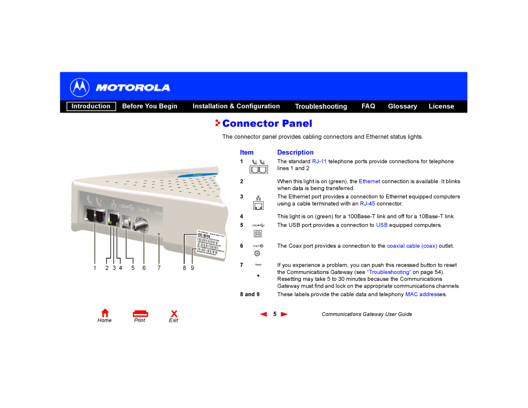
 Connector Panel
The connector panel provides cabling connectors and Ethernet status lights.
Item | Description | ||||||||||
1 |
|
|
|
|
|
|
|
|
|
| The standard |
2 |
|
|
|
|
|
|
|
|
|
| lines 1 and 2 |
|
|
|
|
|
|
|
|
|
| When this light is on (green), the Ethernet connection is available. It blinks | |
|
|
|
|
|
|
|
|
|
|
| when data is being transferred. |
3 |
|
|
|
|
|
|
|
|
|
| The Ethernet port provides a connection to Ethernet equipped computers |
|
|
|
|
|
|
|
|
|
|
| using a cable terminated with an |
|
|
|
|
|
|
|
|
|
|
| |
|
|
|
|
|
|
|
|
|
|
|
|
4This light is on (green) for a
5 |
|
|
|
|
| The USB port provides a connection to USB equipped computers. |
|
|
| ||||
6 |
|
|
|
|
| The Coax port provides a connection to the coaxial cable (coax) outlet. |
|
|
|
|
| ||
7 |
|
|
|
|
| If you experience a problem, you can push this recessed button to reset |
|
|
|
|
|
| the Communications Gateway (see “Troubleshooting” on page 54). |
|
|
|
|
|
| Resetting may take 5 to 30 minutes because the Communications |
|
|
|
|
|
| Gateway must find and lock on the appropriate communications channels. |
8 and 9 | These labels provide the cable data and telephony MAC addresses. | |||||
5 | Communications Gateway User Guide | |||||