Introduction Before You Begin
Installation & Configuration
Troubleshooting FAQ Glossary License
Wall Mounting, continued
6If necessary, seat an anchor in each hole.
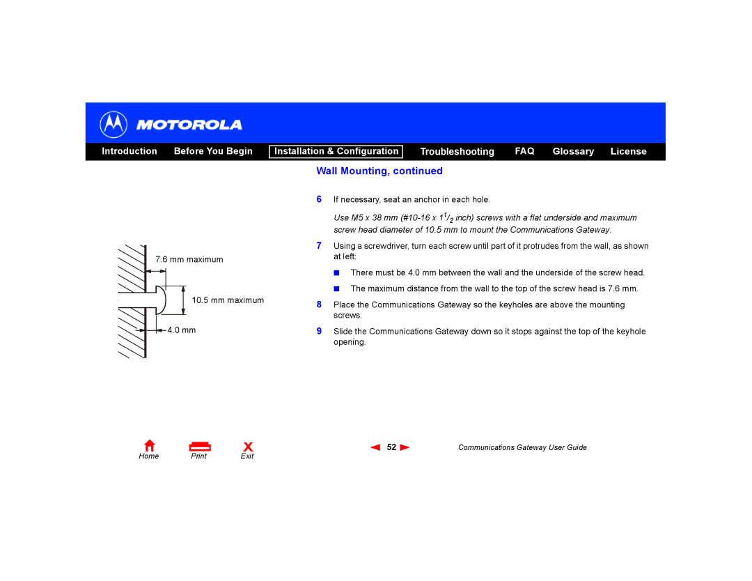
Use M5 x 38 mm
7.6 mm maximum
10.5 mm maximum
4.0 mm
7Using a screwdriver, turn each screw until part of it protrudes from the wall, as shown at left:
■There must be 4.0 mm between the wall and the underside of the screw head.
■The maximum distance from the wall to the top of the screw head is 7.6 mm.
8Place the Communications Gateway so the keyholes are above the mounting screws.
9Slide the Communications Gateway down so it stops against the top of the keyhole opening.
Home | X | 52 | Communications Gateway User Guide | |
Exit |
|
|