O v e r v i e w | 2 - 1 1 |
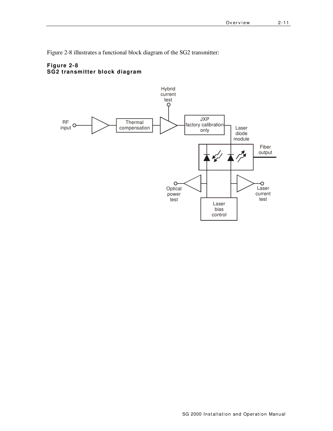
Figure 2-8 illustrates a functional block diagram of the SG2 transmitter:
Figure
SG2 transmitter block diagram
Hybrid current test
|
|
|
|
| |
RF |
|
|
| JXP | |
Thermal | |||||
|
| factory calibration | |||
input | compensation |
|
| ||
|
| only | |||
|
|
|
| ||
|
|
|
|
|
Optical
power
test
Laser bias control
Laser diode module
Fiber output
Laser current test
SG 2000 Installation and O peration Manual
