5 - 2 6 | O p e r a t i o n |
Status Monitoring
Table
Table
Reporting and control provisions
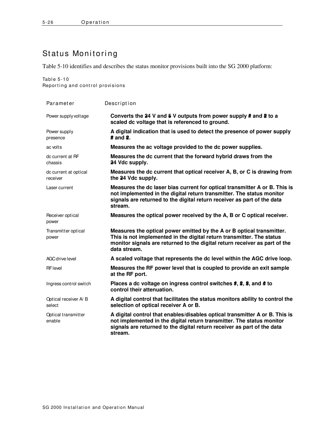
Parameter | Description |
Power supply voltage | Converts the +24 V and +5 V outputs from power supply #1 and #2 to a |
| scaled dc voltage that is referenced to ground. |
Power supply | A digital indication that is used to detect the presence of power supply |
presence | #1 and #2. |
ac volts | Measures the ac voltage provided to the dc power supplies. |
dc current at RF | Measures the dc current that the forward hybrid draws from the |
chassis | +24 Vdc supply. |
dc current at optical | Measures the dc current that optical receiver A, B, or C is drawing from |
receiver | the +24 Vdc supply. |
Laser current | Measures the dc laser bias current for optical transmitter A or B. This is |
| not implemented in the digital return transmitter. The status monitor |
| signals are returned to the digital return receiver as part of the data |
| stream. |
Receiver optical | Measures the optical power received by the A, B or C optical receiver. |
power |
|
Transmitter optical | Measures the optical power emitted by the A or B optical transmitter. |
power | This is not implemented in the digital return transmitter. The status |
| monitor signals are returned to the digital return receiver as part of the |
| data stream. |
AGC drive level | A scaled voltage that represents the dc level within the AGC drive loop. |
RF level | Measures the RF power level that is coupled to provide an exit sample |
| at the RF port. |
Ingress control switch | Places a dc voltage on ingress control switches #1, #2, #3, and #4 to |
| control their attenuation. |
Optical receiver A/B | A digital control that facilitates the status monitors ability to control the |
select | selection of optical receiver A or B. |
Optical transmitter | A digital control that enables/disables optical transmitter A or B. This is |
enable | not implemented in the digital return transmitter. The status monitor |
| signals are returned to the digital return receiver as part of the data |
| stream. |
SG 2000 Installation and O peration Manual
