3 - 4 | B e n c h S e t u p |
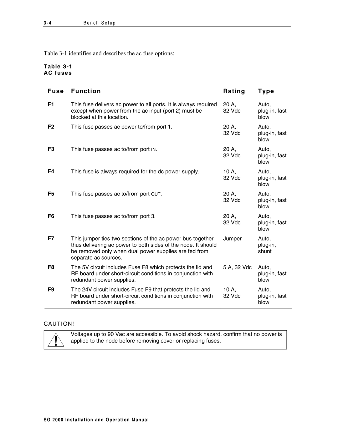
Table
T a b l e 3 - 1
AC f u s e s
Fuse Functi o n | Rati ng | T ype | ||
F1 | This fuse delivers ac power to all ports. It is always required | 20 | A, | Auto, |
| except when power from the ac input (port 2) must be | 32 | Vdc | |
| blocked at this location. |
|
| blow |
F2 | This fuse passes ac power to/from port 1. | 20 | A, | Auto, |
|
| 32 | Vdc | |
|
|
|
| blow |
F3 | This fuse passes ac to/from port IN. | 20 | A, | Auto, |
|
| 32 | Vdc | |
|
|
|
| blow |
F4 | This fuse is always required for the dc power supply. | 10 | A, | Auto, |
|
| 32 | Vdc | |
|
|
|
| blow |
F5 | This fuse passes ac to/from port OUT. | 20 | A, | Auto, |
|
| 32 | Vdc | |
|
|
|
| blow |
F6 | This fuse passes ac to/from port 3. | 20 | A, | Auto, |
|
| 32 | Vdc | |
|
|
|
| blow |
F7 | This jumper ties two sections of the ac power bus together | Jumper | Auto, | |
| thus delivering ac power to both sides of the node. It should |
|
| |
| be removed only when dual power supplies are fed from |
|
| shunt |
| separate ac sources. |
|
|
|
F8 | The 5V circuit includes Fuse F8 which protects the lid and | 5 A, 32 Vdc | Auto, | |
| RF board under |
|
| |
| redundant power supplies. |
|
| blow |
F9 | The 24V circuit includes Fuse F9 that protects the lid and | 10 | A, | Auto, |
| RF board under | 32 | Vdc | |
| redundant power supplies. |
|
| blow |
|
|
|
|
|
CA U T ION!
Voltages up to 90 Vac are accessible. To avoid shock hazard, confirm that no power is applied to the node before removing cover or replacing fuses.
S G 2 0 0 0 I n s t a l l a t i o n a n d O p e r a t i o n M a n u a l
