O p e r a t i o n | 5 - 2 5 |
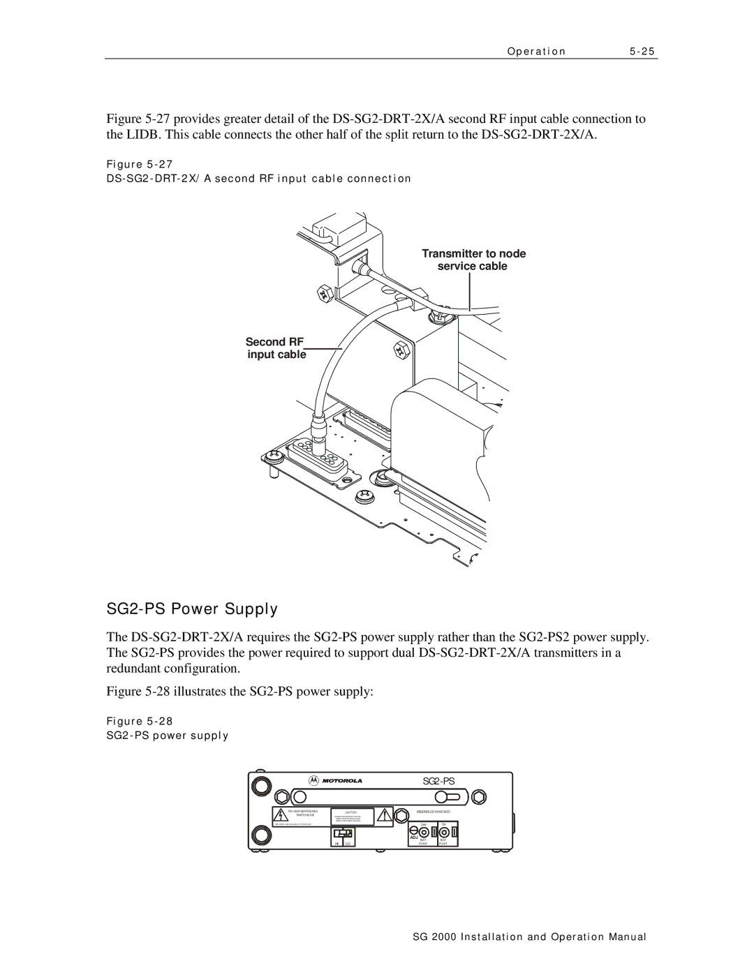
Figure 5-27 provides greater detail of the DS-SG2-DRT-2X/A second RF input cable connection to the LIDB. This cable connects the other half of the split return to the DS-SG2-DRT-2X/A.
Figure
DS-SG2-DRT-2X/A second RF input cable connection
Transmitter to node
service cable
Second RF input cable ![]()
SG2-PS Power Supply
The
Figure 5-28 illustrates the SG2-PS power supply:
Figure
SG2-PS power supply
NO USER SERVICEABLE | CAUTION |
PARTS INSIDE | VOLTAGES IN EXCESS OF 250 VOLTS ARE |
| PRESENT UNDER COVERAND MAY BE |
| PRESENT AFTER POWER IS REMOVED |
SEE INSTA LL ATIO N MANU AL FO R SER VICE
HI LO
SG2-PS
ASSEMBLED IN MEXICO
| 24V |
| 5V |
ADJ TEST |
| TEST | |
| |||
| POINT |
| POINT |
SG 2000 Installation and O peration Manual
