4 - 4 | I n s t a l l a t i o n |
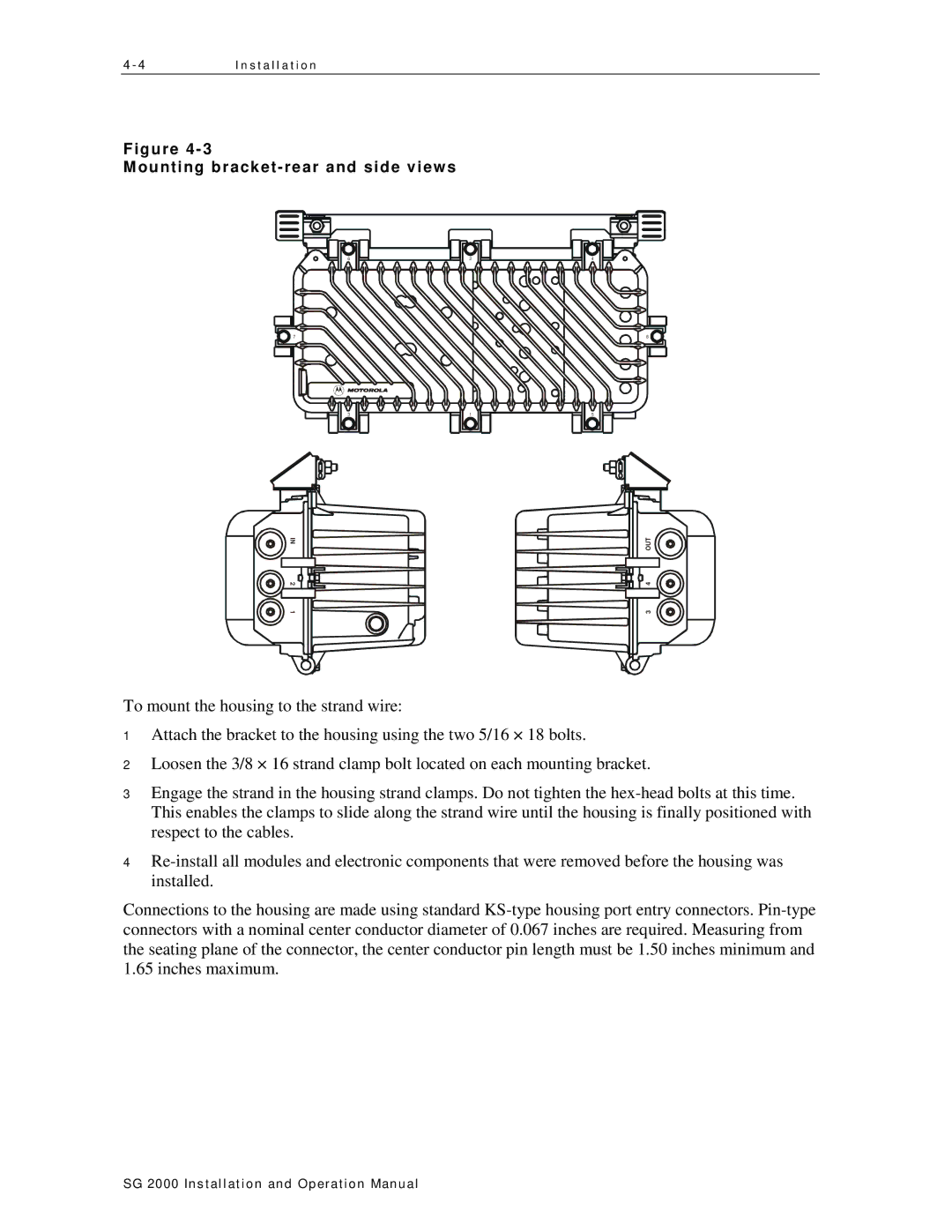
Figure
Mounting bracket-rear and side views
![]()
![]() 7
7
6 | 2 | 4 |
8 |
3 |
|
|
| 1 |
|
|
| 5 |
|
|
|
|
|
|
|
|
|
|
|
|
|
|
|
|
|
|
|
|
|
|
|
|
|
|
|
|
|
|
|
|
|
|
|
|
|
|
|
|
|
|
|
|
|
|
|
|
|
|
|
|
|
|
| IN |
|
|
|
|
|
|
|
|
|
|
|
|
|
| OUT |
|
| ||
|
|
|
|
|
|
|
|
|
|
|
|
|
|
|
|
|
| ||||
|
|
|
|
|
|
|
|
|
|
|
|
|
|
|
| ||||||
|
|
|
| ||||||||||||||||||
|
|
|
|
|
|
|
|
|
|
|
|
|
|
|
|
|
|
|
|
|
|
|
|
|
|
|
|
|
|
|
|
|
|
|
|
|
|
|
|
|
|
|
|
2 | 4 |
1
3
To mount the housing to the strand wire:
1Attach the bracket to the housing using the two 5/16 × 18 bolts.
2Loosen the 3/8 × 16 strand clamp bolt located on each mounting bracket.
3Engage the strand in the housing strand clamps. Do not tighten the
4
Connections to the housing are made using standard
SG 2000 Installation and O peration Manual