O p e r a t i o n | 5 - 5 |
Analog Return Path RF Configuration
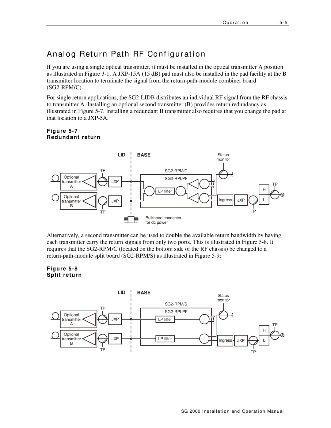
If you are using a single optical transmitter, it must be installed in the optical transmitter A position as illustrated in Figure
For single return applications, the
Figure
Redundant return
LID
| TP | ||
Optional |
|
|
|
|
| JXP | |
transmitter |
|
| |
|
| ||
A |
|
|
|
|
|
| |
|
|
|
|
Optional
transmitterJXP
B
TP
BASE |
|
|
|
|
|
|
| Status |
|
|
|
|
|
| |||||
|
|
|
|
|
|
| monitor |
|
|
|
|
|
| ||||||
|
|
|
|
|
|
|
|
|
|
|
| ||||||||
|
|
|
|
|
|
|
| ||||||||||||
|
|
|
|
|
|
|
|
|
|
|
| ||||||||
|
|
|
|
|
|
| |||||||||||||
|
|
|
|
|
|
|
|
|
|
|
|
|
|
|
|
| TP | ||
|
|
|
|
|
|
|
|
|
|
|
|
|
|
|
|
| |||
|
|
|
|
|
|
|
|
|
|
|
|
|
| ||||||
|
|
|
|
|
|
|
|
|
|
|
|
|
|
|
| H |
|
| |
| LP filter |
|
|
|
|
|
|
|
|
|
|
|
|
|
|
|
| ||
|
|
|
|
|
|
|
|
|
|
|
|
|
|
|
| ||||
|
|
|
|
|
|
|
|
|
|
| |||||||||
|
|
|
|
|
|
|
| Ingress |
| JXP |
|
| L | ||||||
|
|
|
| ||||||||||||||||
|
|
|
|
|
|
|
|
|
| ||||||||||
|
|
|
|
|
|
|
|
|
|
|
|
|
|
|
|
|
|
| |
|
|
|
|
|
|
|
|
|
|
|
|
|
|
|
|
|
| ||
|
|
|
|
|
|
|
|
|
|
|
|
|
| TP | |||||
Bulkhead connector for dc power
Alternatively, a second transmitter can be used to double the available return bandwidth by having each transmitter carry the return signals from only two ports. This is illustrated in Figure
Figure
Split return
LID
| TP | ||
Optional |
|
|
|
|
| JXP | |
transmitter |
|
| |
|
| ||
A |
|
|
|
|
|
| |
|
|
|
|
Optional
transmitterJXP
B
TP
BASE |
|
|
|
|
|
|
| Status |
|
|
|
|
|
| |||
|
|
|
|
| monitor |
|
|
|
|
|
| ||||||
|
|
|
|
|
|
|
|
|
|
|
|
|
|
|
| ||
|
|
|
|
|
|
|
|
|
|
|
|
|
|
|
| ||
|
|
|
|
|
|
|
|
|
|
|
|
|
|
|
| ||
|
|
|
|
|
|
|
|
|
|
|
|
|
|
|
| ||
|
|
|
|
|
|
|
|
|
|
|
|
|
|
|
|
|
|
| LP filter |
|
|
|
|
|
|
|
|
|
|
|
|
| TP | ||
|
|
|
|
|
|
|
|
|
|
|
|
|
| ||||
|
|
|
|
|
|
|
|
|
|
|
|
|
| ||||
|
|
|
|
|
|
|
|
|
|
|
|
|
| ||||
|
|
|
|
|
|
|
|
|
|
|
|
|
|
| |||
|
|
|
|
|
|
|
|
|
|
|
|
|
|
| |||
|
|
|
|
|
|
|
|
|
|
|
|
|
|
| |||
|
|
|
|
|
|
|
|
|
|
|
|
|
| H |
|
| |
|
|
|
|
|
|
|
|
|
|
|
|
|
|
| |||
|
|
|
|
|
|
|
|
|
|
|
|
|
|
|
|
|
|
| LP filter |
|
|
|
|
|
| Ingress |
| JXP |
|
| L | ||||
|
|
|
|
|
|
|
|
|
| ||||||||
|
|
|
|
|
|
|
|
|
|
| |||||||
|
|
|
|
|
|
|
|
|
|
| |||||||
|
|
|
|
|
|
|
|
|
|
|
|
|
|
|
|
|
|
|
|
|
|
|
|
|
|
|
|
|
|
|
|
|
|
|
|
TP
SG 2000 Installation and O peration Manual