O p e r a t i o n | 5 - 2 7 |
Manual Control Board
The SG 2000 manual control board
The MCB board contains two
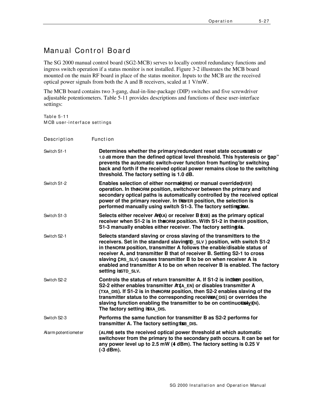
Table
MCB
Description | Function |
Switch | Determines whether the primary/redundant reset state occurs at 0.5 dB or |
| 1.0 dB more than the defined optical level threshold. This hysteresis or “gap” |
| prevents the automatic |
| back and forth if the received optical power remains close to the switching |
| threshold. The factory setting is 1.0 dB. |
Switch | Enables selection of either normal (NORM) or manual override (OVER) |
| operation. In the NORM position, switchover between the primary and |
| secondary optical paths is automatically controlled by the received optical |
| power of the primary receiver. In the OVER position, the selection is |
| performed manually using switch |
Switch | Selects either receiver A (RXA) or receiver B (RXB) as the primary optical |
| receiver when |
| |
Switch | Selects standard slaving or cross slaving of the transmitters to the |
| receivers. Set in the standard slaving (STD_SLV ) position, with switch |
| in the NORM position, transmitter A follows the enable/disable status of |
| receiver A, and transmitter B that of receiver B. Setting |
| slaving (CRS_SLV) causes transmitter B to be on when receiver A is |
| enabled and transmitter A to be on when receiver B is enabled. The factory |
| setting is STD_SLV. |
Switch | Controls the status of return transmitter A. If |
| |
| (TXA_DIS). If |
| transmitter status to the corresponding receiver (TXA_DIS) or overrides the |
| slaving function enabling the transmitter to be on continuously (TXA_EN). |
| The factory setting is TXA_DIS. |
Switch | Performs the same function for transmitter B as |
| transmitter A. The factory setting is TXB_DIS. |
Alarm potentiometer | (ALRM) sets the received optical power threshold at which automatic |
| switchover from the primary to the secondary path occurs. It can be set for |
| any power level up to 2.5 mW (+4 dBm). The factory setting is 0.25 V |
|
SG 2000 Installation and O peration Manual