3 - 1 8 | B e n c h S e t u p |
I n s t a l l i n g t h e D S - S G 2 - D R R B B o a r d O p t i o n
The SG2 Digital Return Redundancy Board (DS-SG2-DRRB) is a fixed plug-in that only provides the capability for RF redundancy to the input of the (DS-SG2-DRT-2X/A). This boards offers full digital return path redundancy when installed in the SG2 fiber optic node.
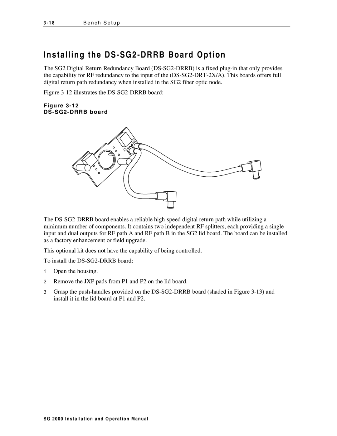
Figure 3-12 illustrates the DS-SG2-DRRB board:
F i g u r e 3 - 1 2
D S - S G 2 - D R R B b o a r d
The DS-SG2-DRRB board enables a reliable high-speed digital return path while utilizing a minimum number of components. It contains two independent RF splitters, each providing a single input and dual outputs for RF path A and RF path B in the SG2 lid board. The board can be installed as a factory enhancement or field upgrade.
This optional kit does not have the capability of being controlled.
To install the DS-SG2-DRRB board:
1Open the housing.
2Remove the JXP pads from P1 and P2 on the lid board.
3Grasp the push-handles provided on the DS-SG2-DRRB board (shaded in Figure 3-13) and install it in the lid board at P1 and P2.
S G 2 0 0 0 I n s t a l l a t i o n a n d O p e r a t i o n M a n u a l