B e n c h S e t u p | 3 - 5 |
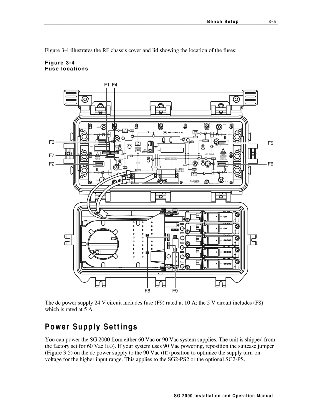
Figure 3-4 illustrates the RF chassis cover and lid showing the location of the fuses:
F i g u r e 3 - 4
F u s e l o c a t i o n s
F1 F4
F3
F7
F2
|
|
|
|
|
|
|
|
| |
|
|
|
|
|
|
|
|
| |
| JXP 1 |
|
|
|
|
|
|
|
|
| FWD EQ |
|
|
|
|
|
|
|
|
H |
|
|
|
|
| FWD EQ |
| H |
|
PORT 1 |
|
|
|
|
|
|
|
| PORT 2 |
L | ON |
|
|
|
| JXP 2 |
| L |
|
|
|
|
|
|
|
|
|
| |
|
|
| ADU |
| TCU | JX P A DU |
| F5 | |
|
|
|
|
|
| ||||
| +24 V DC | MDR |
| ON |
|
|
| ||
FTEC | JXP 1 |
|
|
|
|
|
|
| |
|
| VARILO SSER |
| OFF |
|
|
|
|
|
|
|
|
|
|
|
|
|
| |
|
|
| MAN | SG2- |
|
|
|
|
|
|
|
|
|
|
|
|
|
| |
| IS |
|
|
|
|
| IS | JXP 2 | CAUTION: |
| IS |
|
|
|
|
|
|
| CONTAINS PARTS |
|
|
|
|
|
|
|
| ANDASSEMBLIES | |
REFER TO |
|
|
|
|
|
|
|
| SUSCEPTIBLETO |
|
|
|
|
|
| IS | JXP 4 | DAMAGEBY | |
MANUAL FOR | JXP 3 |
|
|
| STATUS MONITOR |
| ELECTROSTATIC | ||
FUSE VALUES |
|
|
|
|
| ADU |
|
| DISCHARGE( ESD) |
|
| FRB |
|
|
|
|
|
| F6 |
|
|
|
|
| ADU |
|
|
|
|
| JXP 3 |
|
| RPM/* | SG 2000 |
|
|
| |
| RCVR |
|
| JXP 4 |
|
|
| ||
| L |
|
| Optical Node |
|
| L |
| |
|
|
|
|
|
| PORT 4 | |||
PORT 3 |
|
|
|
|
|
|
| H | |
| H |
|
|
|
|
|
|
| |
| EQ |
|
|
|
| FWD EQ |
|
|
|
|
|
|
|
|
|
|
|
| |
|
|
|
|
|
|
|
|
| |
|
|
|
|
|
|
|
| ASSEMBLED IN MEXICO |
|
F8 | F9 |
The dc power supply 24 V circuit includes fuse (F9) rated at 10 A; the 5 V circuit includes (F8) which is rated at 5 A.
P o w e r S u p p l y S e t t i n g s
You can power the SG 2000 from either 60 Vac or 90 Vac system supplies. The unit is shipped from the factory set for 60 Vac (LO). If your system uses 90 Vac powering, reposition the suitcase jumper (Figure
S G 2 0 0 0 I n s t a l l a t i o n a n d O p e r a t i o n M a n u a l