B e n c h S e t u p | 3 - 7 |
Single Power Supply or Commonly Po wered Redundant Supplies
To activate a single power supply or commonly powered redundant supplies, place jumper JP1 (illustrated in Figure
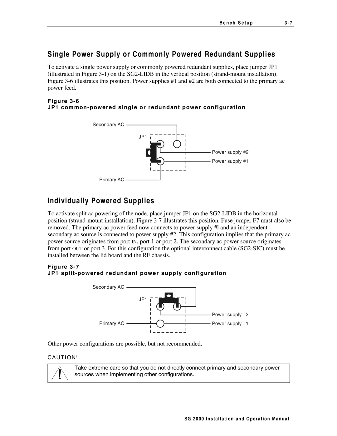
F i g u r e 3 - 6
J P 1 c o m m o n - p o w e r e d s i n g l e o r r e d u n d a n t p o w e r c o n f i g u r a t i o n
Secondary AC
JP1
Power supply #2
Power supply #1
Primary AC
Individually Powered Supplies
To activate split ac powering of the node, place jumper JP1 on the
F i g u r e 3 - 7
J P 1 s p l i t - p o w e r e d r e d u n d a n t p o w e r s u p p l y c o n f i g u r a t i o n
Secondary AC
JP1
Primary AC
Power supply #2
Power supply #1
Other power configurations are possible, but not recommended.
CA U T ION!
Take extreme care so that you do not directly connect primary and secondary power sources when implementing other configurations.
S G 2 0 0 0 I n s t a l l a t i o n a n d O p e r a t i o n M a n u a l