5 - 1 2 | O p e r a t i o n |
Optical input | TP Volts | Output (dBmV) | Output (dBmV) | Comments |
level(dBm/mW) | (1 mW=1 V) | 77 channels | 110 channels |
|
0.6 | 21 | 19 | Normal | |
0.6 | 20 | 18 | Normal | |
0.5 | 19 | 17 | Normal | |
0.5 | 18 | 16 | Normal | |
0.4 | 17 | 16 | Normal | |
| 0.3 | 15 | 13 | High level alarm |
Typical output levels are approximately 2 dB greater than the minimum levels.
Optical modulation index (OMI) for 77 channels (per channel): 0.0403.
OMI for 110 channels (per channel): 0.0337.
Optical transmitter wavelength is 1310 nm.
Bold type indicates default values.
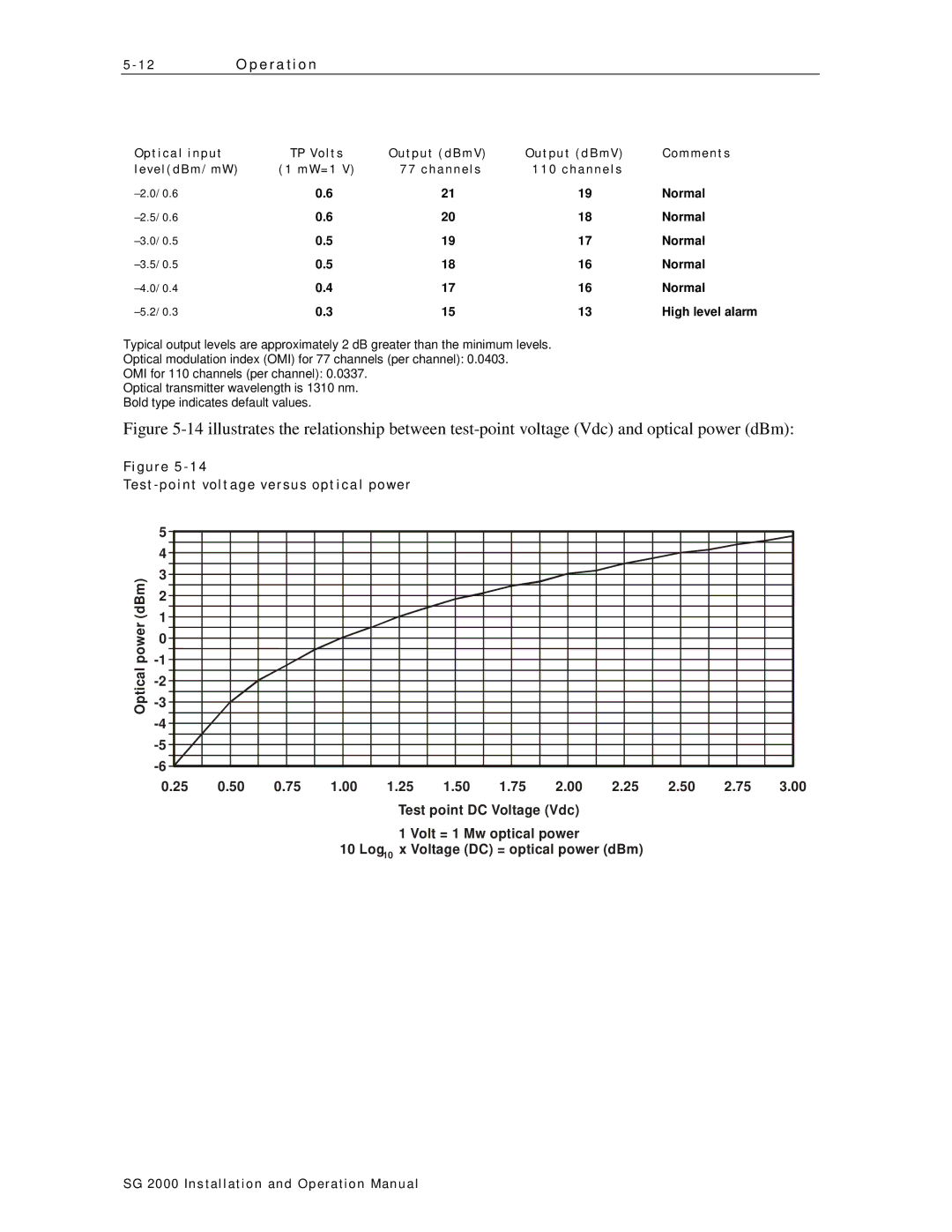
Figure 5-14 illustrates the relationship between test-point voltage (Vdc) and optical power (dBm):
Figure
Test-point voltage versus optical power
| 5 |
|
|
|
|
|
|
|
|
|
|
|
| 4 |
|
|
|
|
|
|
|
|
|
|
|
(dBm) | 3 |
|
|
|
|
|
|
|
|
|
|
|
2 |
|
|
|
|
|
|
|
|
|
|
| |
1 |
|
|
|
|
|
|
|
|
|
|
| |
power | 0 |
|
|
|
|
|
|
|
|
|
|
|
|
|
|
|
|
|
|
|
|
|
| ||
Optical |
|
|
|
|
|
|
|
|
|
|
| |
|
|
|
|
|
|
|
|
|
|
| ||
|
|
|
|
|
|
|
|
|
|
| ||
|
|
|
|
|
|
|
|
|
|
|
| |
|
|
|
|
|
|
|
|
|
|
|
| |
|
|
|
|
|
|
|
|
|
|
|
| |
| 0.25 | 0.50 | 0.75 | 1.00 | 1.25 | 1.50 | 1.75 | 2.00 | 2.25 | 2.50 | 2.75 | 3.00 |
Test point DC Voltage (Vdc)
1 Volt = 1 Mw optical power
10 Log10 x Voltage (DC) = optical power (dBm)
SG 2000 Installation and O peration Manual