3 - 1 2 | B e n c h S e t u p |
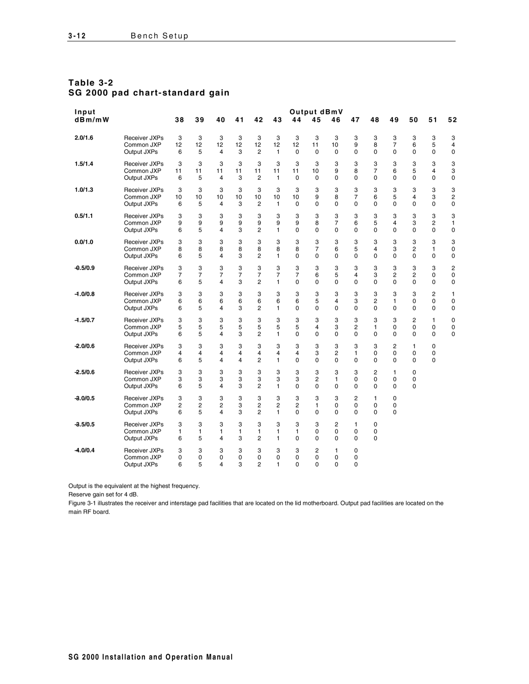
T a b l e 3 - 2
S G 2 0 0 0 p a d c h a r t - s t a n d a r d g a i n
I n p u t |
|
|
|
|
|
|
| O u t p u t d B m V |
|
|
|
|
|
| ||
d B m / m W |
| 3 8 3 9 | 4 0 4 1 4 2 4 3 4 4 4 5 4 6 4 7 4 8 4 9 5 0 5 1 5 2 | |||||||||||||
2.0/1.6 | Receiver JXPs | 3 | 3 | 3 | 3 | 3 | 3 | 3 | 3 | 3 | 3 | 3 | 3 | 3 | 3 | 3 |
| Common JXP | 12 | 12 | 12 | 12 | 12 | 12 | 12 | 11 | 10 | 9 | 8 | 7 | 6 | 5 | 4 |
| Output JXPs | 6 | 5 | 4 | 3 | 2 | 1 | 0 | 0 | 0 | 0 | 0 | 0 | 0 | 0 | 0 |
1.5/1.4 | Receiver JXPs | 3 | 3 | 3 | 3 | 3 | 3 | 3 | 3 | 3 | 3 | 3 | 3 | 3 | 3 | 3 |
| Common JXP | 11 | 11 | 11 | 11 | 11 | 11 | 11 | 10 | 9 | 8 | 7 | 6 | 5 | 4 | 3 |
| Output JXPs | 6 | 5 | 4 | 3 | 2 | 1 | 0 | 0 | 0 | 0 | 0 | 0 | 0 | 0 | 0 |
1.0/1.3 | Receiver JXPs | 3 | 3 | 3 | 3 | 3 | 3 | 3 | 3 | 3 | 3 | 3 | 3 | 3 | 3 | 3 |
| Common JXP | 10 | 10 | 10 | 10 | 10 | 10 | 10 | 9 | 8 | 7 | 6 | 5 | 4 | 3 | 2 |
| Output JXPs | 6 | 5 | 4 | 3 | 2 | 1 | 0 | 0 | 0 | 0 | 0 | 0 | 0 | 0 | 0 |
0.5/1.1 | Receiver JXPs | 3 | 3 | 3 | 3 | 3 | 3 | 3 | 3 | 3 | 3 | 3 | 3 | 3 | 3 | 3 |
| Common JXP | 9 | 9 | 9 | 9 | 9 | 9 | 9 | 8 | 7 | 6 | 5 | 4 | 3 | 2 | 1 |
| Output JXPs | 6 | 5 | 4 | 3 | 2 | 1 | 0 | 0 | 0 | 0 | 0 | 0 | 0 | 0 | 0 |
0.0/1.0 | Receiver JXPs | 3 | 3 | 3 | 3 | 3 | 3 | 3 | 3 | 3 | 3 | 3 | 3 | 3 | 3 | 3 |
| Common JXP | 8 | 8 | 8 | 8 | 8 | 8 | 8 | 7 | 6 | 5 | 4 | 3 | 2 | 1 | 0 |
| Output JXPs | 6 | 5 | 4 | 3 | 2 | 1 | 0 | 0 | 0 | 0 | 0 | 0 | 0 | 0 | 0 |
Receiver JXPs | 3 | 3 | 3 | 3 | 3 | 3 | 3 | 3 | 3 | 3 | 3 | 3 | 3 | 3 | 2 | |
| Common JXP | 7 | 7 | 7 | 7 | 7 | 7 | 7 | 6 | 5 | 4 | 3 | 2 | 2 | 0 | 0 |
| Output JXPs | 6 | 5 | 4 | 3 | 2 | 1 | 0 | 0 | 0 | 0 | 0 | 0 | 0 | 0 | 0 |
Receiver JXPs | 3 | 3 | 3 | 3 | 3 | 3 | 3 | 3 | 3 | 3 | 3 | 3 | 3 | 2 | 1 | |
| Common JXP | 6 | 6 | 6 | 6 | 6 | 6 | 6 | 5 | 4 | 3 | 2 | 1 | 0 | 0 | 0 |
| Output JXPs | 6 | 5 | 4 | 3 | 2 | 1 | 0 | 0 | 0 | 0 | 0 | 0 | 0 | 0 | 0 |
Receiver JXPs | 3 | 3 | 3 | 3 | 3 | 3 | 3 | 3 | 3 | 3 | 3 | 3 | 2 | 1 | 0 | |
| Common JXP | 5 | 5 | 5 | 5 | 5 | 5 | 5 | 4 | 3 | 2 | 1 | 0 | 0 | 0 | 0 |
| Output JXPs | 6 | 5 | 4 | 3 | 2 | 1 | 0 | 0 | 0 | 0 | 0 | 0 | 0 | 0 | 0 |
Receiver JXPs | 3 | 3 | 3 | 3 | 3 | 3 | 3 | 3 | 3 | 3 | 3 | 2 | 1 | 0 |
| |
| Common JXP | 4 | 4 | 4 | 4 | 4 | 4 | 4 | 3 | 2 | 1 | 0 | 0 | 0 | 0 |
|
| Output JXPs | 6 | 5 | 4 | 4 | 2 | 1 | 0 | 0 | 0 | 0 | 0 | 0 | 0 | 0 |
|
Receiver JXPs | 3 | 3 | 3 | 3 | 3 | 3 | 3 | 3 | 3 | 3 | 2 | 1 | 0 |
|
| |
| Common JXP | 3 | 3 | 3 | 3 | 3 | 3 | 3 | 2 | 1 | 0 | 0 | 0 | 0 |
|
|
| Output JXPs | 6 | 5 | 4 | 3 | 2 | 1 | 0 | 0 | 0 | 0 | 0 | 0 | 0 |
|
|
Receiver JXPs | 3 | 3 | 3 | 3 | 3 | 3 | 3 | 3 | 3 | 2 | 1 | 0 |
|
|
| |
| Common JXP | 2 | 2 | 2 | 3 | 2 | 2 | 2 | 1 | 0 | 0 | 0 | 0 |
|
|
|
| Output JXPs | 6 | 5 | 4 | 3 | 2 | 1 | 0 | 0 | 0 | 0 | 0 | 0 |
|
|
|
Receiver JXPs | 3 | 3 | 3 | 3 | 3 | 3 | 3 | 3 | 2 | 1 | 0 |
|
|
|
| |
| Common JXP | 1 | 1 | 1 | 1 | 1 | 1 | 1 | 0 | 0 | 0 | 0 |
|
|
|
|
| Output JXPs | 6 | 5 | 4 | 3 | 2 | 1 | 0 | 0 | 0 | 0 | 0 |
|
|
|
|
| Receiver JXPs | 3 | 3 | 3 | 3 | 3 | 3 | 3 | 2 | 1 | 0 |
|
|
|
|
|
| Common JXP | 0 | 0 | 0 | 0 | 0 | 0 | 0 | 0 | 0 | 0 |
|
|
|
|
|
| Output JXPs | 6 | 5 | 4 | 3 | 2 | 1 | 0 | 0 | 0 | 0 |
|
|
|
|
|
Output is the equivalent at the highest frequency.
Reserve gain set for 4 dB.
Figure 3-1 illustrates the receiver and interstage pad facilities that are located on the lid motherboard. Output pad facilities are located on the main RF board.
S G 2 0 0 0 I n s t a l l a t i o n a n d O p e r a t i o n M a n u a l