S p e c i f i c a t i o n s | A - 7 |
Table
Table
Current requirements
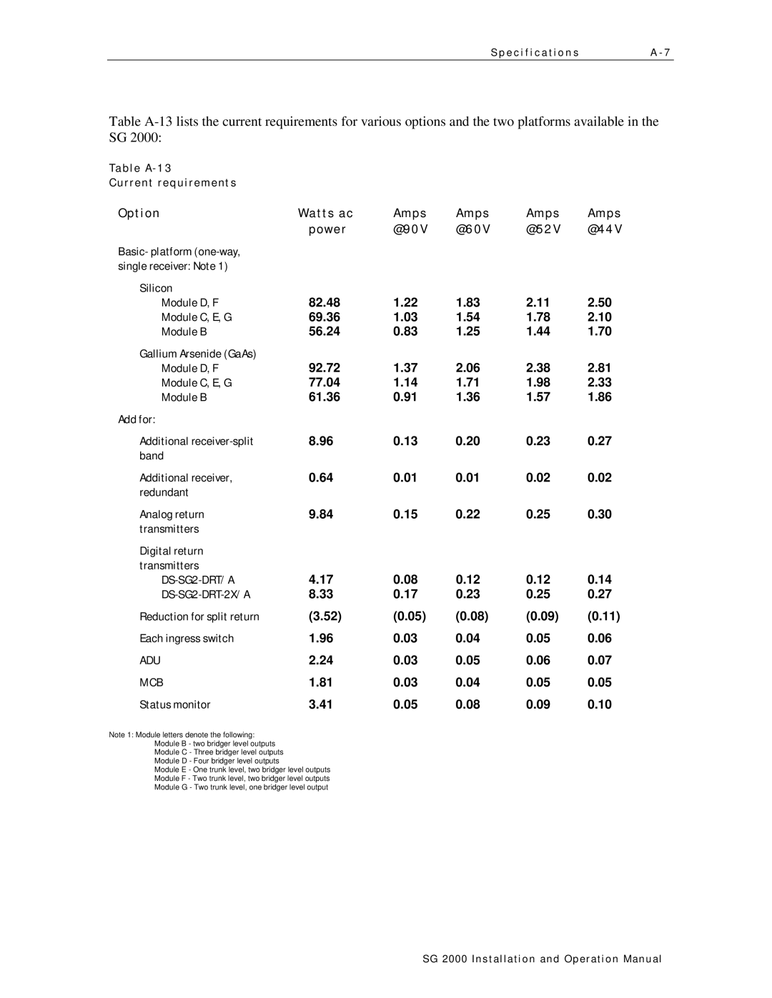
Option | Watts ac | Amps | Amps | Amps | Amps |
| power | @90V | @60V | @52V | @44V |
Basic- platform |
|
|
|
|
|
single receiver: Note 1) |
|
|
|
|
|
Silicon |
|
|
|
|
|
Module D, F | 82.48 | 1.22 | 1.83 | 2.11 | 2.50 |
Module C, E, G | 69.36 | 1.03 | 1.54 | 1.78 | 2.10 |
Module B | 56.24 | 0.83 | 1.25 | 1.44 | 1.70 |
Gallium Arsenide (GaAs) |
|
|
|
|
|
Module D, F | 92.72 | 1.37 | 2.06 | 2.38 | 2.81 |
Module C, E, G | 77.04 | 1.14 | 1.71 | 1.98 | 2.33 |
Module B | 61.36 | 0.91 | 1.36 | 1.57 | 1.86 |
Add for: |
|
|
|
|
|
Additional | 8.96 | 0.13 | 0.20 | 0.23 | 0.27 |
band |
|
|
|
|
|
Additional receiver, | 0.64 | 0.01 | 0.01 | 0.02 | 0.02 |
redundant |
|
|
|
|
|
Analog return | 9.84 | 0.15 | 0.22 | 0.25 | 0.30 |
transmitters |
|
|
|
|
|
Digital return |
|
|
|
|
|
transmitters |
|
|
|
|
|
4.17 | 0.08 | 0.12 | 0.12 | 0.14 | |
| 8.33 | 0.17 | 0.23 | 0.25 | 0.27 |
Reduction for split return | (3.52) | (0.05) | (0.08) | (0.09) | (0.11) |
Each ingress switch | 1.96 | 0.03 | 0.04 | 0.05 | 0.06 |
ADU | 2.24 | 0.03 | 0.05 | 0.06 | 0.07 |
MCB | 1.81 | 0.03 | 0.04 | 0.05 | 0.05 |
Status monitor | 3.41 | 0.05 | 0.08 | 0.09 | 0.10 |
Note 1: Module letters denote the following:
Module B - two bridger level outputs
Module C - Three bridger level outputs
Module D - Four bridger level outputs
Module E - One trunk level, two bridger level outputs
Module F - Two trunk level, two bridger level outputs
Module G - Two trunk level, one bridger level output
SG 2000 Installation and O peration Manual
