B e n c h S e t u p | 3 - 1 9 |
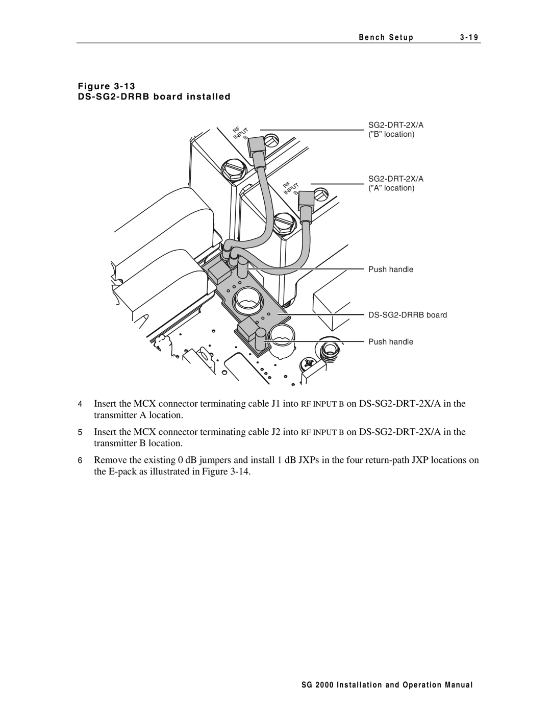
F i g u r e 3 - 1 3
D S - S G 2 - D R R B b o a r d i n s t a l l e d
Push handle
Push handle
4Insert the MCX connector terminating cable J1 into RF INPUT B on
5Insert the MCX connector terminating cable J2 into RF INPUT B on
6Remove the existing 0 dB jumpers and install 1 dB JXPs in the four
S G 2 0 0 0 I n s t a l l a t i o n a n d O p e r a t i o n M a n u a l
