User Manual for the NETGEAR 7200 Series Layer 2 Managed Switch Software
Quick Startup Physical Port Data
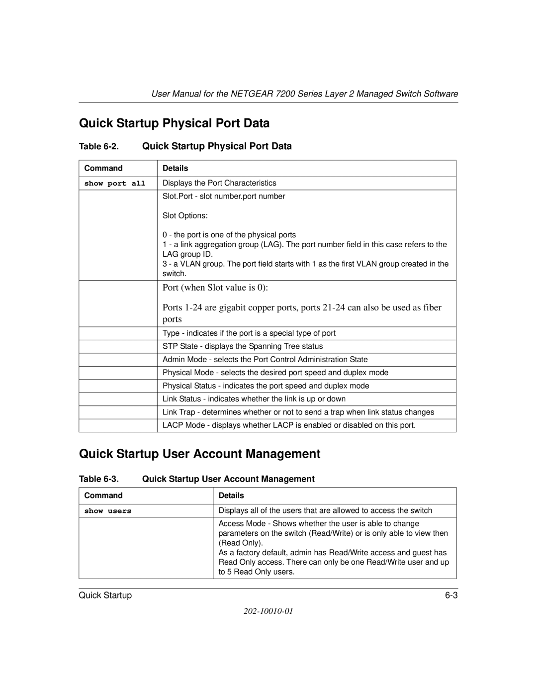
Table 6-2. Quick Startup Physical Port Data
Command | Details |
|
|
show port all | Displays the Port Characteristics |
| Slot.Port - slot number.port number |
| Slot Options: |
| 0 - the port is one of the physical ports |
| 1 - a link aggregation group (LAG). The port number field in this case refers to the |
| LAG group ID. |
| 3 - a VLAN group. The port field starts with 1 as the first VLAN group created in the |
| switch. |
|
|
| Port (when Slot value is 0): |
| Ports |
| ports |
|
|
| Type - indicates if the port is a special type of port |
|
|
| STP State - displays the Spanning Tree status |
|
|
| Admin Mode - selects the Port Control Administration State |
|
|
| Physical Mode - selects the desired port speed and duplex mode |
|
|
| Physical Status - indicates the port speed and duplex mode |
|
|
| Link Status - indicates whether the link is up or down |
|
|
| Link Trap - determines whether or not to send a trap when link status changes |
|
|
| LACP Mode - displays whether LACP is enabled or disabled on this port. |
|
|
Quick Startup User Account Management
Table | Quick Startup User Account Management | ||
Command |
| Details |
|
|
|
|
|
show users |
| Displays all of the users that are allowed to access the switch |
|
|
| Access Mode - Shows whether the user is able to change |
|
|
| parameters on the switch (Read/Write) or is only able to view then |
|
|
| (Read Only). |
|
|
| As a factory default, admin has Read/Write access and guest has |
|
|
| Read Only access. There can only be one Read/Write user and up |
|
|
| to 5 Read Only users. |
|
|
|
|
|
|
|
|
|
Quick Startup | |||