201-10301-02, May
Statement of Conditions
Trademarks
FCC Caution
EN 55 022 Declaration of Conformance
Voluntary Control Council for Interference Vcci Statement
Bestätigung des Herstellers/Importeurs
Certificate of the Manufacturer/Importer
201-10301-02, May
Contents
Chapter Wireless Configuration
Chapter Firewall Protection Content Filtering
Chapter Virtual Private Networking
Chapter Advanced Configuration
Appendix C Preparing Your Network
Appendix D Firewall Log Formats
Appendix F Virtual Private Networking
Glossary
Xiv Contents
Audience, Scope, Conventions, and Formats
Chapter About This Manual
Typographical Conventions
Manual Scope
How to Use This Manual
Printing a Page in the Html View
How to Print this Manual
Printing a Chapter
Printing the Full Manual
About This Manual
Chapter Introduction
Key Features of the FWG114P
Full Routing on Both the Broadband and Serial Ports
802.11g and 802.11b Wireless Networking
Flash memory for firmware upgrade NAT off classical routing
Virtual Private Networking
Wireless Multimedia WMM Support
Powerful, True Firewall with Content Filtering
Autosensing Ethernet Connections with Auto Uplink
Security
Extensive Protocol Support
Netgear Related Products
Easy Installation and Management
Package Contents
LED Descriptions
FWG114P v2 Rear Panel
Router to a broadband modem
Introduction
Computer Network Configuration Requirements
Connecting the FWG114P v2 to the Internet
What You Will Need Before You Begin
Cabling and Computer Hardware Requirements
Where Do I Get the Internet Configuration Parameters?
Internet Configuration Requirements
Record Your Internet Connection Information
Verify That Basic Requirements Are Met
Connecting the FWG114P v2 Wireless Firewall/Print Server
Local Port
Verify the connections to the firewall
It starts automatically
LOG in to the Wireless FIREWALL/PRINT Server
Login Result
RUN the Setup Wizard to Connect to the Internet
FWG114P v2 Setup Wizard Auto Detection
Basic Setup Troubleshooting Tips
Make sure the network settings of the computer are correct
Be sure to restart your network in the correct sequence
Setup Wizard menu for PPPoE login accounts
Wizard-Detected Login Account Setup
Connecting the FWG114P v2 to the Internet
10 Setup Wizard menu for Dynamic IP address
Wizard-Detected Dynamic IP Account Setup
11 Setup Wizard menu for Fixed IP address
Wizard-Detected Fixed IP Account Setup
Connect the Firewall to your Isdn or dial-up modem
Configure the Serial Port of the Firewall
12 Serial Internet Connection configuration menu
Connect to the Internet to test your configuration
Testing Your Internet Connection
13 Browser-based configuration Basic Settings menu
Manually Configuring Your Internet Connection
How to Manually Configure the Primary Internet Connection
Connecting the FWG114P v2 to the Internet
Observing Performance, Placement, and Range Guidelines
Chapter Wireless Configuration
FWG114P v2 wireless data security options
Implementing Appropriate Wireless Security
Wireless Settings menu
Understanding Wireless Settings
Wireless Card Access List
Wireless Network. The station name of the FWG114P
Wireless Access Point
Security Options
Feature Default Factory Settings Ssid Netgear
Default Factory Settings
Authentication
Before You Change the Ssid and WEP Settings
WPA or WPA2 Radius Settings
WEP Encryption Keys
How to Set Up and Test Basic Wireless Connectivity
Wireless Station Access menu
How to Restrict Wireless Access by MAC Address
To configure WEP data encryption, follow these steps
How to Configure WEP
Wireless Settings menu WEP
Click Wireless Settings in the main menu of the FWG114P
How to Configure WPA with Radius
Wireless Settings menu WPA with Radius
How to Configure WPA2 with Radius
Wireless Settings menu WPA2 with Radius
How to Configure WPA and WPA2 with Radius
Wireless Settings menu WPA and WPA2 with Radius
How to Configure WPA-PSK
Wireless Settings menu WPA-PSK
10 Wireless Settings menu WPA2-PSK
How to Configure WPA2-PSK
How to Configure WPA-PSK and WPA2-PSK
11 Wireless Settings menu WPA-PSK and WPA2-PSK
Modem
Chapter Serial Port Configuration
Auto-Rollover
Dial-in
How to Configure a Serial Port Modem
Configuring a Serial Port Modem
Basic Requirements for Serial Port Modem Configuration
Basic Requirements for Auto-Rollover
Configuring Auto-Rollover
How to Configure Auto-Rollover
Auto-Rollover configuration menu
Configuring Dial-in on the Serial Port
Basic Requirements for Dial-in
How to Configure Dial-in
Basic Requirements for LAN-to-LAN Connections
Configuring LAN-to-LAN Settings
How to Configure LAN-to-LAN Connections
LAN-to-LAN configuration menu
Serial Port Configuration
Using the Block Sites Menu to Screen Content
Chapter Firewall Protection Content Filtering
Firewall Protection and Content Filtering Overview
Block Sites menu
These steps are discussed below
Services and Rules Regulate Inbound and Outbound Traffic
Defining a Service
Using Inbound/Outbound Rules to Block or Allow Services
Rules menu
Inbound Rules Port Forwarding
Examples of Using Services and Rules to Regulate Traffic
Example Port Forwarding to a Local Public Web Server
Rule example Videoconference from Restricted Addresses
This rule is shown in Figure
Service example port forwarding for VPN when NAT is Off
Outbound Rules Service Blocking or Port Filtering
Rule example Blocking Instant Messenger
Other Rules Considerations
Rules Menu Options
Order of Precedence for Rules
Schedule menu
Using a Schedule to Block or Allow Content or Traffic
Getting E-Mail Notifications of Event Logs and Alerts
Setting the Time Zone
E-mail menu
Firewall Protection and Content Filtering
10 Logs menu
Viewing Logs of Web Access or Attempted Web Access
Log action buttons
What to Include in the Event Log
Log action buttons are described in Table
Firewall Protection and Content Filtering
Printing Options
Chapter Print Server
FWG114P v2 supports these methods for printing
For Macintosh computers LPR printing
Port
For Windows XP and 2000, Use TCP/IP LPR Printing
Click Add a printer. Click Next to proceed
Complete the Add Standard TCP/IP Printer Port Wizard
Add Printer Wizard Install Printer Software
Print Server
For Windows 95/98/Me, Use the Netgear Printer Port Driver
Set up the Netgear printer port driver
Print Server
Printing from the Macintosh
Windows Printer Port Management
Print Port Configuration menu
Troubleshooting the Print Server
Windows Add Printer Wizard
Windows Printer Properties
Print Server
Print Server
Chapter Virtual Private Networking
Overview of FWG114P v2 Policy-Based VPN Configuration
Using Automatic Key Management
Using Policies to Manage VPN Traffic
IKE Policy Configuration Menu
IKE Policies’ Automatic Key and Authentication Management
Field Description General
IKE Policy Configuration Fields
Field Description Remote
VPN Auto Policy Menu
VPN Policy Configuration for Auto Key Negotiation
VPN Auto Policy fields are defined in the following table
VPN Auto Policy Configuration Fields
Authenticating Header AH
Netbios Enable
VPN Policy Configuration for Manual Key Exchange
VPN Manual Policy Menu
VPN Manual Policy fields are defined in the following table
VPN Manual Policy Configuration Fields
Value in its Authentication Algorithm Key In field
Value in its Encryption Algorithm Key Out field
Certificate Revocation List CRL
How to Use the VPN Wizard to Configure a VPN Tunnel
Walk-Through of Configuration Scenarios on the FWG114P
VPN Wizard Start Screen
Remote IP
Summary screen below displays
VPN Wizard Summary
10 VPN Consortium Scenario
Vpnc Scenario 1 Gateway to Gateway with Preshared Secrets
Scenario 1 FWG114P v2 to FWG114P v2 with Preshared Secrets
11 LAN to LAN VPN access from an FWG114P v2 to an FWG114P
13 LAN IP configuration menu
14 Scenario 1 IKE Policy
Set up the IKE Policy illustrated below on the FWG114P
Address
Set up the FWG114P v2 VPN -Auto Policy illustrated below
How to Check VPN Connections
16 VPN Consortium Scenario
Vpnc Scenario 2 Gateway-to-Gateway with Certificates
Scenario 2 FWG114P v2 to FWG114P v2 with Certificates
Install the trusted CA certificate for the Trusted Root CA
Obtain a root certificate
Create a certificate request for the FWG114P
FWG114P
Highlight, copy and paste this data into a text file
19 Self Certificate Requests table
20 Self Certificates table
Set up Certificate Revocation List CRL checking
Summary
Configuration Profile
Netgear VPN Client to FWG114P
22 Addressing and Subnet Used for Examples
Step-By-Step Configuration of FWG114P v2 Gateway
23 Netgear FWG114P v2 IKE Policy Configuration
Virtual Private Networking
24 VPN Auto Policy settings
Virtual Private Networking
Step-By-Step Configuration of the Netgear VPN Client
Configure the Connection Network Settings
Install the Netgear VPN Client Software on the PC
27 My Identity
Configure the Connection Identity Settings
Click Pre-Shared Key
Select the Enable Perfect Forward Secrecy PFS check box
This example, enter this pre-shared key in this field
Hr5xb84l6aa9r6
31 Connection Security Policy Authentication Phase
Configure the Connection Security Policy
Check the Encapsulation Protocol ESP check box
32 Connection Security Policy Key Exchange Phase
Save the VPN Client Settings
Configure the Global Policy Settings
Choose FWG114P
Testing the VPN Connection
From the Client PC to the FWG114P
From the FWG114P v2 to the Client PC
Monitoring the PC VPN Connection
35 Connection Monitor screen
Viewing the FWG114P v2 VPN Status and Log Information
36 FWG114P v2 VPN Status screen
Viewing Wireless Firewall/Print Server Status Information
Chapter Maintenance
Status Fields
Router Status screen shows the following parameters
Dhcp
Connection Status Fields
Click WAN Status to display the WAN connection status
This screen shows the following statistics
Router Statistics Fields
Click Show Statistics to display router usage statistics
Connection Status action buttons
WAN Status action buttons are described in Table
Viewing a List of Attached Devices
Upgrading the Router Software
Configuration File Management
Settings Backup menu
Restoring and Backing Up the Configuration
Erasing the Configuration
Changing the Administrator Password
Maintenance
Connect Automatically, as Required
Chapter Advanced Configuration
Using the WAN Setup Options
Respond to Ping on Internet WAN Port
Setting Up a Default DMZ Server
Setting the WAN Port Speed
How to Configure Dynamic DNS
Setting the MTU Size
10-4 Advanced Configuration
Configuring LAN TCP/IP Setup Parameters
Using the LAN IP Setup Options
10-6 Advanced Configuration
Using Address Reservation
Using the Router as a Dhcp server
Configuring Static Routes
Static Route Entry and Edit Menu
Enabling Remote Management Access
UPnP Menu
Using Universal Plug and Play UPnP
Advanced Wireless Settings menu
Advanced Wireless Settings
RTS Threshold
WMM support
Fragmentation Length
Beacon Interval
10-14 Advanced Configuration
Basic Functioning
Chapter Troubleshooting
Power LED Not On
LAN or Internet Port LEDs Not On
LEDs Never Turn Off
Troubleshooting the Web Configuration Interface
Troubleshooting the ISP Connection
Testing the LAN Path to Your Router
Troubleshooting a TCP/IP Network Using a Ping Utility
Click on OK You should see a message like this one
If the path is working, you see this message
If the path is not working, you see this message
Testing the Path from Your Computer to a Remote Device
Problems with Date and Time
Restoring the Default Configuration and Password
11-8 Troubleshooting
Data and Routing
Appendix a Technical Specifications
Protocols PPP over Ethernet PPPoE
Protocols
Interface Specifications
Wireless
10BASE-T or 100BASE-Tx, RJ-45
Antenna External detachable 5 dBi omnidirectional
Related Publications Basic Router Concepts
What is a Router?
Appendix B Networks, Routing, and Firewall Basics
Is normally written as
Routing Information Protocol
IP Addresses and the Internet
Three Main Address Classes
Subnet Addressing
Netmask
Combined with
Equals
Example of Subnetting a Class B Address
Netmask Formats
Netmask Notation Translation Table for One Octet
Private IP Addresses
Single IP Address Operation Using NAT
Single IP Address Operation Using NAT
Domain Name Server
MAC Addresses and Address Resolution Protocol
Related Documents
Internet Security and Firewalls
IP Configuration by Dhcp
Denial of Service Attack
What is a Firewall?
Ethernet Cabling
Stateful Packet Inspection
Category 5 Cable Quality
Table B-1 UTP Ethernet cable wiring, straight-through
Figure B-1illustrates straight-through twisted pair cable
Inside Twisted Pair Cables
Uplink Switches, Crossover Cables, and MDI/MDIX Switching
Networks, Routing, and Firewall Basics
Networks, Routing, and Firewall Basics
Preparing Your Computers for TCP/IP Networking
Appendix C Preparing Your Network
Install or Verify Windows Networking Components
Configuring Windows 95, 98, and Me for TCP/IP Networking
Preparing Your Network
Selecting Windows’ Internet Access Method
Enabling Dhcp to Automatically Configure TCP/IP Settings
Verifying TCP/IP Properties
Configuring Windows NT, 2000 or XP for IP Networking
Installing or Verifying Windows Networking Components
From the Apple menu, select Control Panels, then TCP/IP
Configuring the Macintosh for TCP/IP Networking
MacOS 8.6 or
MacOS
Verifying TCP/IP Properties for Macintosh Computers
Verifying the Readiness of Your Internet Account
Are Login Protocols Used?
What Is Your Configuration Information?
Mail.xxx.yyy.com
Preparing Your Network
Restarting the Network
Action List
Appendix D Firewall Log Formats
Field List
Outbound Log
Format is
Inbound Log
Other IP Traffic
Operations that the router initiates are logged Format is
Router Operation
Common attacks and scans are logged
Other Connections and Traffic to this Router
DoS Attack/Scan
Datetimepkttype Srcip Dstipaction
All Web Sites and News Groups Visited
Access Block Site
System Admin Sessions
Date Time Event Direction Service Description
Policy Administration LOG
Firewall Log Formats
Wireless Networking Overview
Appendix E Wireless Networking Basics
Infrastructure Mode
This chapter provides an overview of Wireless networking
Network Name Extended Service Set Identification Essid
Authentication and WEP Data Encryption
Ad Hoc Mode Peer-to-Peer Workgroup
Open System Authentication
Authentication
Figure E-1 Open system authentication
Shared Key Authentication
Overview of WEP Parameters
Figure E-2 Shared key authentication
Key Size
WEP Configuration Options
Wireless Channels
WPA Wireless Security
How Does WPA Compare to WEP?
How Does WPA Compare to Ieee 802.11i?
What are the Key Features of WPA Security?
Wireless Networking Basics
Figure E-3 WPA Overview
Login Authentication
Figure E-4 802.1x Authentication Sequence
Access point replies with an EAP-request identity message
WPA Data Encryption Key Management
Temporal Key Integrity Protocol Tkip
Product Support for WPA
Is WPA Perfect?
New WPA information element
WPA two-phase authentication
Open system, then 802.1x EAP with Radius or preshared key
Michael
Changes to Wireless Client Programs
Appendix F Virtual Private Networking
What is a VPN?
IPSec Security Features
What is IPSec and How Does It Work?
IPSec Components
IPSec contains the following elements
Encapsulating Security Payload ESP
IKE Security Association
Authentication Header AH
Mode
Key Management
Understand the Process Before You Begin
Vpnc Example Network Interface Addressing
VPN Process Overview
Interfaces and Addresses
Subnet Addressing
Setting Up a VPN Tunnel Between Gateways
WAN Internet/Public and LAN Internal/Private Addressing
IPSec Security Association IKE VPN Tunnel Negotiation Steps
Vpnc IKE Security Parameters
Vpnc IKE Phase I Parameters
Additional Reading
Testing and Troubleshooting
Vpnc IKE Phase II Parameters
Virtual Private Networking
Table G-1 Summary
Configuration Template
Log in to
Figure G-2 Netgear FVS318 VPN Settings Pre-Configuration
Figure G-3 Netgear FVS318 VPN Settings part 1 Main Mode
Figure G-4 Netgear FVS318 VPN Settings part 2 Main Mode
Figure G-5 Netgear FVS328 IKE Policy Configuration Part
Step-By-Step Configuration of FWG114P Gateway B
Figure G-6 Netgear FVS328 IKE Policy Configuration Part
Figure G-8 Netgear FVS328 VPN Auto Policy part
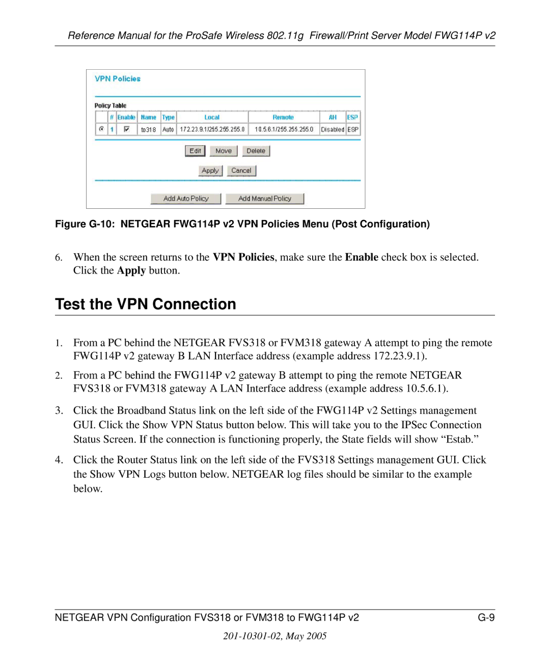
Figure G-9 Netgear FWG114P v2 VPN Auto Policy part
Test the VPN Connection
Netgear VPN Configuration FVS318 or FVM318 to FWG114P
Table H-1 Summary
Table H-1
Figure H-2 Dynamic DNS Setup menu
Step-By-Step Configuration of FVS318 or FVM318 Gateway a
Figure H-3 Netgear FVS318 VPN Settings Pre-Configuration
Figure H-4 Netgear FVS318 VPN Settings part 1 Main Mode
Figure H-5 Netgear FVS318 VPN Settings part 2 Main Mode
Figure H-6 Netgear FVS328 IKE Policy Configuration Part
Step-By-Step Configuration of FVS328 Gateway B
Figure H-7 Netgear FVS328 IKE Policy Configuration Part
Figure H-9 Netgear FVS328 VPN Auto Policy part
Figure H-10 Netgear FVS328 VPN Auto Policy part
Test the VPN Connection
201-10301-02, May
Glossary
802.11e Standard
Bandwidth
Collision avoidance
DNS Domain Name System Encryption Key
Gateway
IP Internet Protocol address
PHY
Plug and Play
Satellite broadband
TCP/IP
War Driving
Wi-Fi Protected Access and Ieee 802.11i Comparison
Wi-Fi Protected Access in Mixed Mode Deployment