Parts and their functions
Audio function section (1)
2
3
4
6
7 | 5 |
1 |
|
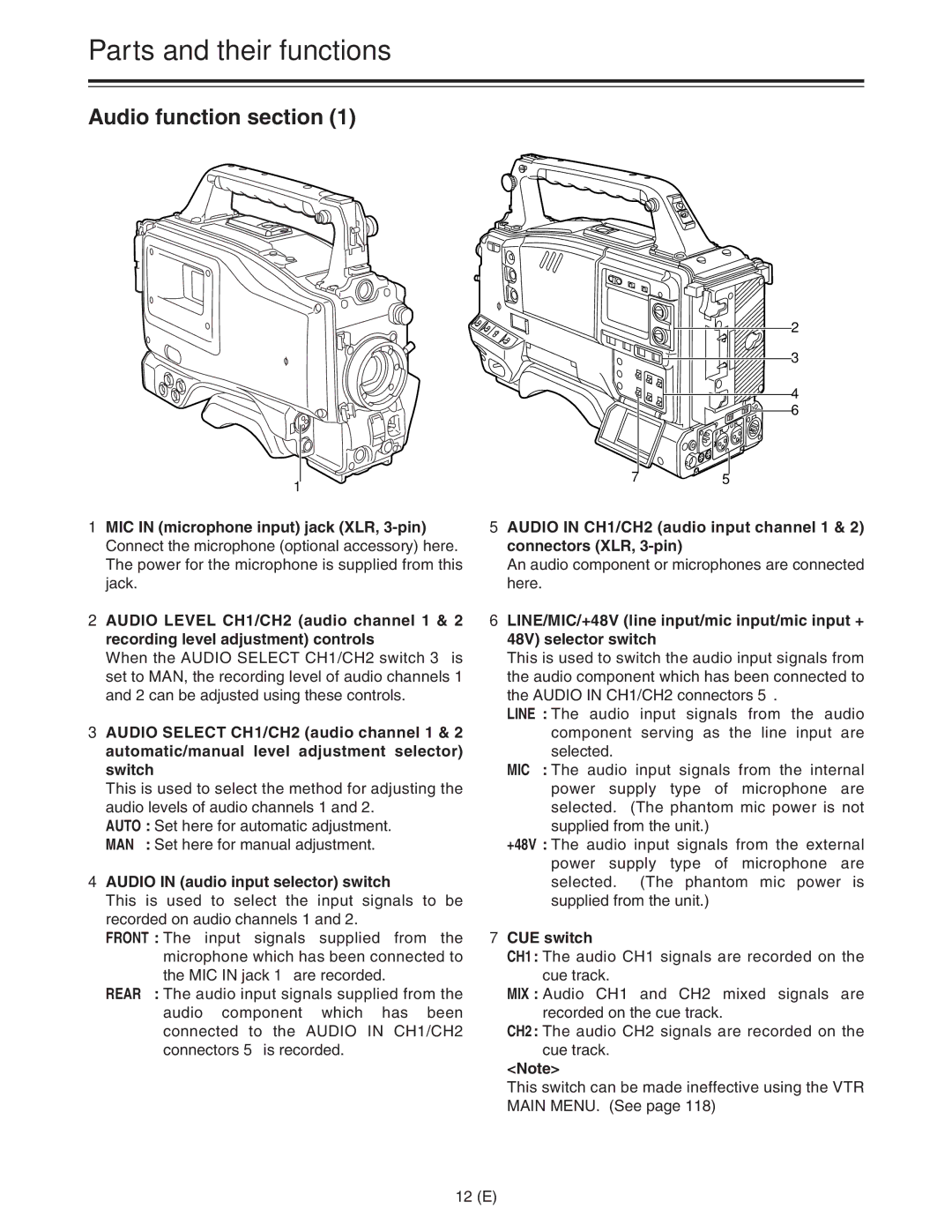
1MIC IN (microphone input) jack (XLR,
2AUDIO LEVEL CH1/CH2 (audio channel 1 & 2 recording level adjustment) controls
When the AUDIO SELECT CH1/CH2 switch 3 is set to MAN, the recording level of audio channels 1 and 2 can be adjusted using these controls.
3AUDIO SELECT CH1/CH2 (audio channel 1 & 2 automatic/manual level adjustment selector) switch
This is used to select the method for adjusting the audio levels of audio channels 1 and 2.
AUTO : Set here for automatic adjustment.
MAN : Set here for manual adjustment.
4AUDIO IN (audio input selector) switch
This is used to select the input signals to be recorded on audio channels 1 and 2.
FRONT : The input signals supplied from the microphone which has been connected to the MIC IN jack 1 are recorded.
REAR : The audio input signals supplied from the audio component which has been connected to the AUDIO IN CH1/CH2 connectors 5 is recorded.
5AUDIO IN CH1/CH2 (audio input channel 1 & 2) connectors (XLR,
An audio component or microphones are connected here.
6LINE/MIC/+48V (line input/mic input/mic input + 48V) selector switch
This is used to switch the audio input signals from the audio component which has been connected to the AUDIO IN CH1/CH2 connectors 5.
LINE : The audio input signals from the audio component serving as the line input are selected.
MIC : The audio input signals from the internal power supply type of microphone are selected. (The phantom mic power is not supplied from the unit.)
+48V : The audio input signals from the external power supply type of microphone are selected. (The phantom mic power is supplied from the unit.)
7CUE switch
CH1: The audio CH1 signals are recorded on the cue track.
MIX : Audio CH1 and CH2 mixed signals are recorded on the cue track.
CH2: The audio CH2 signals are recorded on the cue track.
<Note>
This switch can be made ineffective using the VTR MAIN MENU. (See page 118)
12 (E)
