Viewfinder screen status displays
1Extender display
This appears when the lens extender is being used.
2Shutter speed/mode display
This indicates the shutter speed or shutter mode setting.
The unit in which the shutter speed is displayed can be set on the VF DISPLAY screen of FILM (CAM) MAIN MENU 2.
O OFF (no display):
The shutter is not used.
O 1/100, 1/120, 1/250 1/500, 1/1000, 1/2000 (180d, 172.8d, 144d, 120d, 90d, 45d): Shutter speeds in the fixed mode
O 3.0d to 350.0d/0.8% to 97.2% (SYNCHRO
SCAN):
Selection of synchro scan mode
In the synchro scan mode, “Y” appears immediately in front of the number displayed.
3Remaining tape display
During recording, this shows the remaining tape (in minutes) in the VTR. When less than two minutes of tape remain, the figure starts flashing.
4Battery voltage display
This indicates the battery voltage (V) during operation. The voltage is displayed as a percentage when a digital battery is used.
5Filter display
This indicates the type of filter selected.
6White balance memory display
This indicates the automatic adjustment memory selected for the white balance.
A:The WHITE BAL switch has been set to “A.”
B:The WHITE BAL switch has been set to “B.”
P:The WHITE BAL switch has been set to “PRST.”
7Gain display
This indicates the gain (dB) of the video amplifier which was set using the GAIN switch.
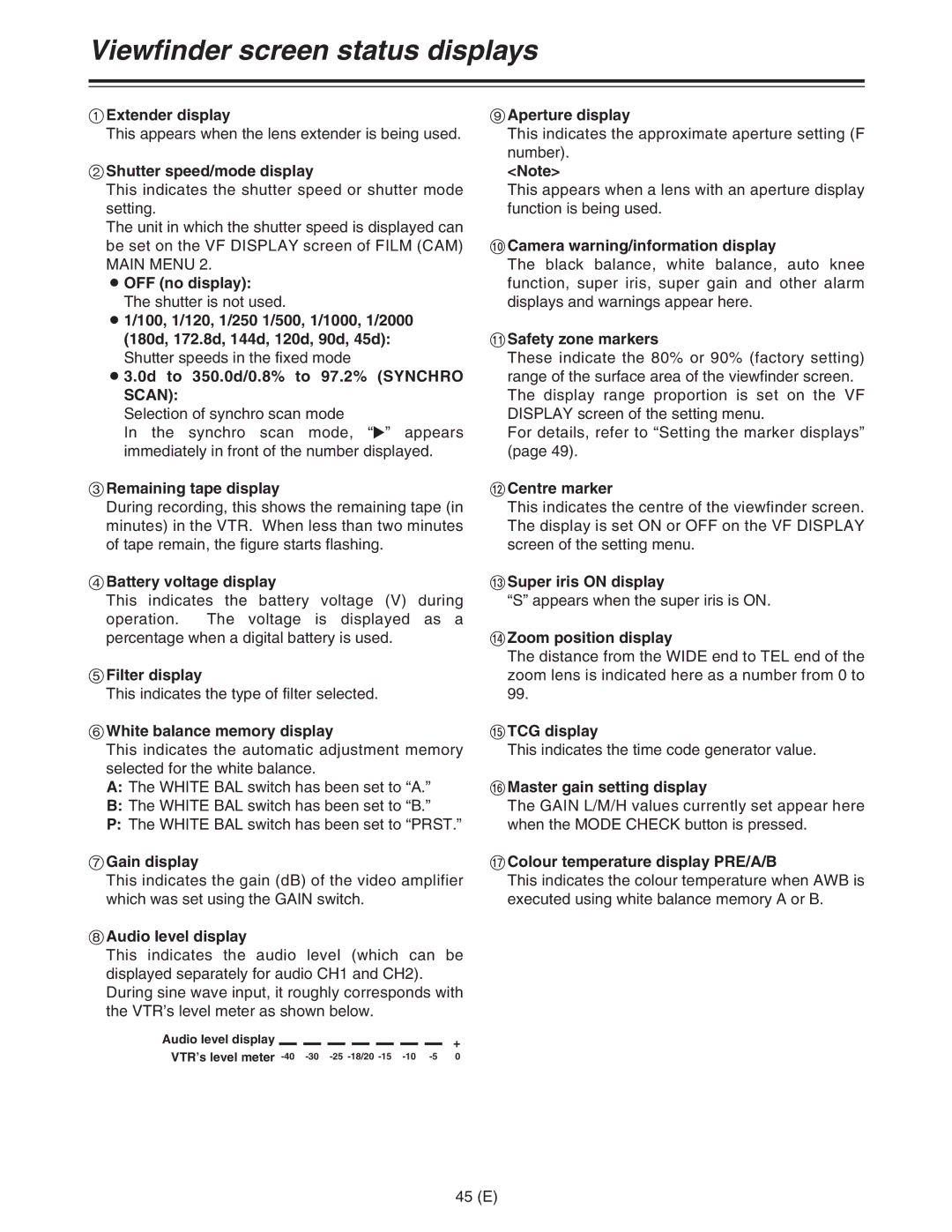
8Audio level display
This indicates the audio level (which can be displayed separately for audio CH1 and CH2). During sine wave input, it roughly corresponds with the VTR’s level meter as shown below.
Audio level display |
|
|
|
|
|
|
|
|
|
|
|
|
| + |
|
|
|
|
|
|
| ||||||||
VTR’s level meter | 0 | |||||||||||||
9Aperture display
This indicates the approximate aperture setting (F number).
<Note>
This appears when a lens with an aperture display function is being used.
:Camera warning/information display
The black balance, white balance, auto knee function, super iris, super gain and other alarm displays and warnings appear here.
;Safety zone markers
These indicate the 80% or 90% (factory setting) range of the surface area of the viewfinder screen. The display range proportion is set on the VF DISPLAY screen of the setting menu.
For details, refer to “Setting the marker displays” (page 49).
<Centre marker
This indicates the centre of the viewfinder screen. The display is set ON or OFF on the VF DISPLAY screen of the setting menu.
=Super iris ON display
“S” appears when the super iris is ON.
>Zoom position display
The distance from the WIDE end to TEL end of the zoom lens is indicated here as a number from 0 to 99.
?TCG display
This indicates the time code generator value.
@Master gain setting display
The GAIN L/M/H values currently set appear here when the MODE CHECK button is pressed.
AColour temperature display PRE/A/B
This indicates the colour temperature when AWB is executed using white balance memory A or B.
45 (E)