HOTWIRE� Hdsl Standalone Termination Unit
Copyright E 1999 Paradyne Corporation All rights reserved
Important Safety Instructions
EMI Warnings
Contents
Initial Startup and Configuration
Messages and Troubleshooting
Standards Compliance for Snmp Traps
About This Guide
Document Purpose and Intended Audience
Document Summary
Product-Related Documents
About the Hotwire Standalone Termination Unit
Hotwire 7984 Termination Unit Features
Hdsl Overview
About the Hotwire 7984 Standalone Termination Unit
Network Configuration
CO Site
Front Panel LED Status Indicators
Rear Panel Interface Connections
Snmp Trap Support
Snmp Management Capabilities
Management Information Base MIB Support
Network
About the Hotwire 7984 Standalone Termination Unit
Using the Asynchronous Terminal Interface
User Interface Access
Communication Port Settings
Login
Initiating an ATI Session
Area
Select
Screen
Function
Main Status Test
Keys
Screen Work Areas
Input
Field Value Choices Messages
Navigating the Screens
Keyboard Keys
Press
Screen Function Keys
For the screen function Select Press Enter to
Switching Between Screen Work Areas
Example
Ending an ATI Session
Using the Asynchronous Terminal Interface
Initial Startup and Configuration
Overview
Connecting Power to the Unit
+24 Vdc Power Supply Pinouts
Connecting to the Network
Connecting to a System Terminal
Entering Identity Information
Main Menu → Control → Change
Identity
Procedure
Choosing a Configuration Mode
Configuring the Unit Using the Configuration Menus
Configuration Option Area Configuration Option Set
Configuring the Unit Using the Internal Switches
Handling Precautions for STATIC-SENSITIVE Devices
Switchpack Locations
Switchpack S1 & S2
OFF = Switchpacks Disabled
Switchpack Definitions
Switchpack S1 Definitions Switch # Allows you to
OFF = Internal Clock
Switchpack S2 Definitions Switch # Allows you to
Load Configuration from
Accessing and Displaying Configuration Options
Main Menu → Configuration Load Configuration From
If you select Then
Main Menu → Configuration → Default Factory
Configuration Edit/Display
Main Menu → Configuration → Current Configuration
Select To Access To Configure
Configuration Loader
Main Menu → Configuration → Configuration Loader
Completed successfully
Saving Configuration Options
Save Configuration
Download Code
Download Code
Main Menu → Control → Download Code
DSL
Monitoring the Unit
What to Monitor
Viewing System and Test Status
Main Menu → Status → System and Test Status
System and Test Status Health and Status SELF-TEST Results
Health and Status
Yyyyyyyy
Call your service
Self-Test Results
Test Status
Test Status Messages Meaning
Viewing Network Error Statistics
Main Menu → Status → Performance → Network Error Statistics
Network Error Statistics
Viewing Network Performance Statistics
This Field Contains
This Field Contains
Viewing DSX-1 Performance Statistics
DSX-1 Performance Statistics
This Field Contains
Viewing 7984 Standalone Termination Unit LEDs
Main Menu → Status → Display LEDs
General
Standalone Termination Unit LEDs
Type
LED is Indicating
Monitoring the Unit
Main Menu →
Testing
Accessing the Test Menu
Test
Running Network Tests
Main Menu → Test → Network & DSX Tests
Network & DSX Tests
Line Loopback
Repeater Loopback
T1 to T1 Repeater Loopback
T1 to V.35 Repeater Loopback
DTE Loopback
Send Remote Line Loopback
Send and Monitor
Main Menu → Test → Device Tests
Device Tests
Lamp Test
Device Tests
Ending an Active Test
Telco-Initiated Tests
Telco-Initiated Line Loopback
Telco-Initiated Payload Loopback
Telco-Initiated Remote Line Loopback
Messages and Troubleshooting
Configuring Snmp Traps
Snmp Traps Options
Device Messages
Device Messages 1 What Message Indicates What To Do
Device Messages 2 What Message Indicates What To Do
Troubleshooting
Troubleshooting 1 Symptom Possible Cause Solutions
Troubleshooting 2 Symptom Possible Cause Solutions
ATI Access Levels
Security
Tables
Creating a Login
Administer Logins
Login Entry
On the Login Entry screen, for Enter
Deleting a Login
Controlling Snmp Access
Assigning Snmp Community Names and Access Types
Resetting the Termination Units COM Port or Factory Defaults
Main Menu → Configuration → Management → Security Menu
If entering yes to prompt Then
IP Addressing
Selecting an IP Addressing Scheme
IP Addressing Example
Peer IP Address Assignments
Configuration Option Tables
Configuration Options in , Initial Startup and Configuration
Main Menu → Configuration → Current Configuration →
Network Interface Options Menu
Table A-1. Network Interface Options 1
DSL Line Rate Possible Settings 400, 528, 784, 1040
Table A-1. Network Interface Options 2
Circuit Identifier
Table A-2. DSX-1 Interface Options 1
Main Menu → Configuration → Load Configuration From →
DSX-1 Interface Options
Port Status
Table A-2. DSX-1 Interface Options 2
System Options Menu
DSL Mode
Test Timeout
Table A-3. System Options 1
Table A-3. System Options 2
Telco Initiated Loopback
Remote Telco Loopback
Table A-4. Communication Port Options 1
Port Type Possible Settings Asynchronous, Synchronous
Communication Port
Port Use
Table A-4. Communication Port Options 2
Inactivity Timeout Terminal Use Only
Login Required Terminal Use Only
Port Access Level Terminal Use Only
Table A-4. Communication Port Options 3
Management and Communication Options Menu
Telnet Session Options
Telnet Session Options
Table A-5. Telnet Session Options
Communication Protocol Options
Communication Protocol Options
PPP
Default Network Destination
Node IP Address Possible Settings 000.000.000.000 ±
Node Subnet Mask Possible Settings 000.000.000.000 ±
Table A-6. Communication Protocol Options 1
Table A-6. Communication Protocol Options 2
Communication Port Link Protocol
Table A-7. General Snmp Management Options 1
Community Name Possible Settings Ascii text field, Public
General Snmp Management Options
Snmp Management
Name 1 Access
Name 2 Access
Table A-7. General Snmp Management Options 2
NMS IP Validation
Snmp NMS Security Options
Table A-8. Snmp NMS Security Options 1
Number of Managers
Access Level
Table A-8. Snmp NMS Security Options 2
Snmp Traps
Snmp Traps Options
Table A-9. Snmp Traps Options 1
Number of Trap Managers
Table A-9. Snmp Traps Options 2
NMS n Destination
Enterprise Specific Traps
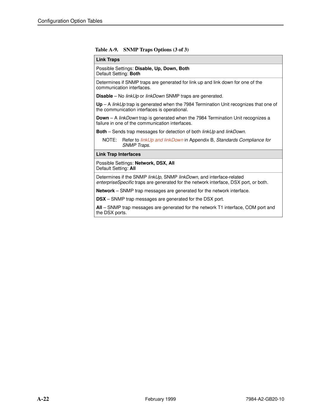
Link Traps Possible Settings Disable, Up, Down, Both
Table A-9. Snmp Traps Options 3
Link Trap Interfaces
Snmp Traps
AuthenticationFailure
Standards Compliance for Snmp Traps
WarmStart
LinkUp and linkDown
LinkUp/Down Variable-Bindings
Enterprise-Specific Traps
DSX
Cables and Pin Assignments
T1 Network Interface
Position Modular Plug Unkeyed DB15 Socket
Table C-2. DSL Network Interface Connector
Signal Pin Number
DSL Network Interface Cable
Figure C-3. COM Port-to-PC Cable Feature Number 7900-F1-507
COM Port Interface Cable
Table C-3. COM Port Connector J6 Signal Direction Pin Number
Power Input Connector
Optional Power Cable
Table C-4. DC Power Connector Signal Pin Number
Technical Specifications
Specifications Criteria
Technical Specifications
Bridged tap
Glossary
511
COM port
Frame relay
Factory defaults
Ethernet
703
Loopback
Reset
IP address
Router
SES
Telnet
Index
IN-1
IN-2
IN-3
IN-4